W W W . K A A R T A . C O M
7
2.
Remove the four (4) M8 Fasteners, split lockwashers, and flat washers from each
corner of the Vehicle Mount Base Assembly and set aside (Figure 4).
3.
Using a 4mm hex allen key, loosen all sixteen (16) M6 x 16mm long button head
fasteners securing the four (4) Base Reinforcement plates to the Vehicle Mount
Base Assembly. Loosen fasteners just enough so that the Base Reinforcement
Plates can slide along the side rails (approximately 1 full turn of the fastener).
Do
not remove the button head fasteners completely.
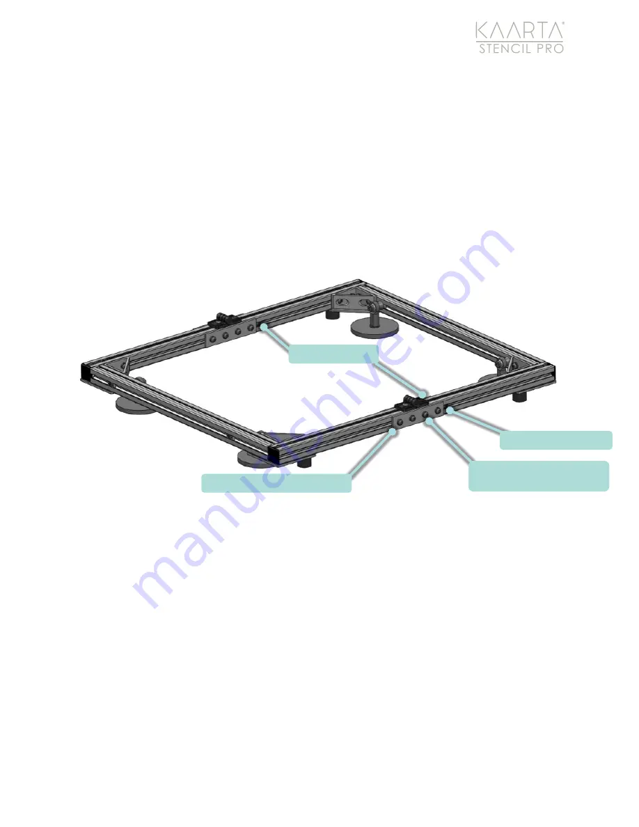
Slide each Base
Reinforcement plate until each plate hits the stop on the rear side rail. This is the
operational position of the plates. Tighten all sixteen (16) M6 button head
fasteners until M6 split lockwashers have been flattened. Maintain reinforcement
plate contact with the stops during this process (Figure 5).
Figure 5: Vehicle Mount Base Assembly in operational configuration.
S t e p 2 : A s s e m b l e t h e U p p e r V e h i c l e M o u n t A s s e m b l y
1.
Using a 3mm hex allen key, loosen all eight (8) M5 flat head fasteners that secure
the four (4) Upper Support Arms to their corresponding pivot joints (approximately
½
turn of the fastener).
Do not remove the M5 fasteners completely
, only
loosen enough so the Upper Support Arms are free to rotate and access to the M8
socket head fasteners that secure the pivot joints to the Top Cross Rail is obtained
(Figure 6).
BASE REINFORCEMENT PLATE (4X)
M6 X 16MM LONG BUTTON HEAD
FASTERNER (16X)
BASE REINFORCEMENT
REAR SIDE RAIL


