background image


W W W . K A A R T A . C O M  


9 3  


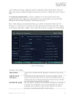
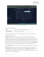
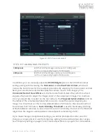
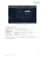
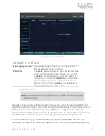
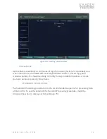
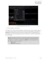
Figure 65: Subsample settings. 

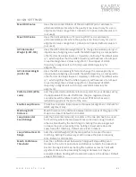
SUBSAMPLE  SE TTINGS


Subsampling Method 

Select subsampling method from drop-down menu: 
Percent, Random, Spatial or Octree. 

Parameter 

If 

percent

, adjust parameter by changing decimal value 

to percent of points remaining (default is 0.10 

or 10%

). 

If 

random

, adjust parameter by changing number of 

the total points remaining. If 

spatial

, adjust parameter 

by changing the distance between points (in meters; 
default is 0.10 

or 10cm

). If 

octree

, adjust parameter by 

changing the level (1-12; default is 11). 

Convert to  LAS 


You can convert a point cloud into an LAS file, an open, binary format designed for the 
interchange and archiving of lidar point cloud data. It is specified by the American Society 
for Photogrammetry and Remote Sensing (ASPRS) and is regarded as an industry 
standard for lidar data. Conversion of a PLY pointcloud to an LAS pointcloud will embed 
the GNSS offsets and zone from the scan_info.yaml file into the LAS pointcloud. 

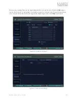
Prior to converting a point cloud to an LAS file, you must subsample the data. See 
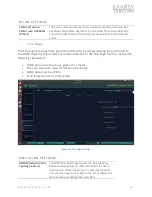
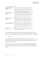
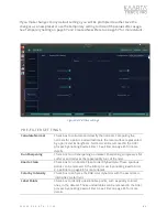
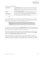
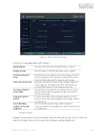
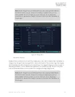
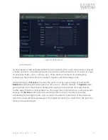
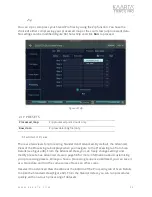
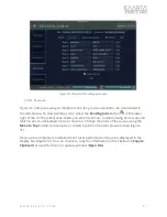
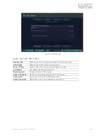
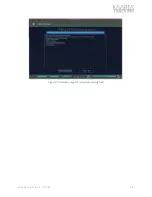
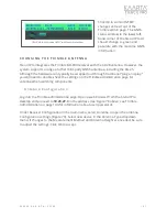
Subsample on page 91 for more information. Convert to LAS has one preset (Figure 66). 

Note: 

It is recommended that you Subsample prior to Converting your 

data to an LAS.  

Summary of Contents for STENCIL PRO

Page 1: ...K A A R T A E N G I N E U S P A T E N T N O 1 0 9 6 2 3 7 0 A N D O T H E R P A T E N T S P E N D I N G USER GUIDE U G S 3 2 1 0 2 1 0 0 2 0 8 2 2 ...

Page 2: ...200m and a data rate of 600 000 points per second Stencil Pro produces a highly accurate 3D model in minutes New advancements are backed by proven Kaarta technology quality and accuracy Stencil Pro s intuitive user interface UI makes data capture and processing simple The user experience includes one button scanning real time scan monitoring and streamlined post processing options for maximizing d...

Page 3: ...with a second clean microfiber towel S C O P E These instructions are for Stencil Pro Software Version S3 21 02 1 Software Updates and Hardware Upgrades are available for all Stencils Email stencilsupport kaarta com with the Stencil Pro Serial Number for the best options for your particular unit See Serial Number on page 4 about the different ways to find your Serial Number on Stencil Pro componen...

Page 4: ...erial number can also be found on the About tab of Device Settings through the Stencil Pro UI See About on page 22 for more information on identifying your Stencil Pro Serial Number via the Stencil Pro Main Gallery options Figure 1 Stencil Pro serial number location on back side of Controller C A S E S T U D I E S For examples of Case Studies for Stencil Pro please contact the Kaarta Stencil Pro s...

Page 5: ...locations Addition of Processing Tooltips Tooltips have been added to post processing fields and tasks for improved transparency Image Sorting Images are now sorted in order of time in the Image Mgmt tab Enhancements Kaarta Engine Stability Kaarta Engine stability enhancements have been implemented Localization Option in Playback A new post processing feature Localization has been added to Playbac...

Page 6: ... Box 8 Identifying Stencil Pro Components 8 Front of Scanner 8 Back of Scanner 8 Front of Controller 9 Side Top of Controller 9 External Scanner Components 10 External Controller Components 12 Chapter 2 14 Before You Begin Mapping 14 Charge Batteries 14 Connect Peripherals 14 Supply Power To The Controller 15 Power on Scanner and Connect Data To From Controller 15 Chapter 3 17 Stencil Pro Operatio...

Page 7: ...5 57 Playback and Processing 57 Processing 57 Chapter 6 100 Getting Best Results with GNSS 100 PPK Best Practices 100 Configuring NTRIP 103 Changing the Trimble Antenna 107 Using Data From Your Own Base Station 108 Chapter 7 111 Troubleshooting 111 Verify Scanner Is Receiving Images 111 Verify GNSS Is Communicating 112 IP Addresses for Stencil Pro 114 ...

Page 8: ...ate c V Mount Batteries 2 US Only d Carrying Bag 3 20 to 5 8 11 Adapter 4 Vehicle and Hand Carry Umbilical Cables between Controller and Scanner 5 Wireless Keyboard and Mouse 6 iPad and Wi Fi dongle for wireless display and operation 7 V Mount Battery Charger AC 8 Controller AC Adapter 9 Shipping Case 10 Tactical Accessories Bag 11 Manfrotto Monopod 1 4 2 1b 1a 2a 2b 2d Side 3 5 6 7 9 8 10 2c Top ...

Page 9: ... O C O M P O N E N T S F R O N T O F S C A N N E R B A C K O F S C A N N E R 32 LINE SCANNER ANTENNA BRACKET SCAN BUTTON DATA CONNECTOR PANO COLOR CAMERA POWER CONNECTOR PANO COLOR CAMERA PANO COLOR CAMERA THREADED BASE PANO COLOR CAMERA ODOMETRY CAMERA GNSS ANTENNA ...

Page 10: ... E R S I D E T O P O F C O N T R O L L E R LED STATUS LIGHTS POWER SWITCH SCANNER DATA CONNECTOR HDMI PORT SHORE POWER CONNECTOR V MOUNT BATTERY PLATE BATTERY RELEASE V MOUNT BATTERY PLATE AIR VENTS SCANNER POWER CONNECTOR USB C PORT SCAN BUTTON USB A PORTS ...

Page 11: ...ton The LED ring around the button turns from green teal to yellow while saving then returns to a blue ready state Wait for the blue indicator before powering off or beginning a new scan Note Supply power to the scanner by connecting it to the controller through their respective Power Connectors SCANNER CONNECTORS AND PORTS Power Connector Power is supplied to the scanner from the controller s Sca...

Page 12: ...ng Blue Kaarta Software Ready 6 Satellites Kaarta Software Ready 6 Satellites Green Ready to Scan GPS Lock 6 Satellites Scanning GPS Lock 6 Satellites Teal Ready to Scan GPS Lock 6 Satellites Scanning GPS Lock 6 Satellites Yellow Processing Orange Scanning Error Disk Critical 5GB Not Licensed Scanner Error Pink Disk Level Low 25GB Disk Very Low 12 5GB Lost Communication with Controller ...

Page 13: ...main in the V mounts If shore power is not connected the system utilizes battery power The V mount batteries are not charged via Stencil Pro s shore power connection and should be charged with the supplied AC battery charger Down Off Turn the switch down to turn off the controller CONTROLLER CONNECTORS AND PORTS USB C Port The USB C connector can be used for high speed USB 3 0 drives for fast data...

Page 14: ...t Battery BAT 1 Right Battery BAT 2 Internal Compute r Power CTL Scanner Power SENSOR CONTROLLER LED STATUS COLORS Left Right Battery SOLID Internal Computer Scanner SOLID Red 15 Red Error Off Yellow 20 Green 20 Green Normal Operation Blue AC Power Usage Off No battery ...

Page 15: ...ys the battery s remaining power You should continue to monitor the battery level during scanning If outside the United States compatible Li Ion V mount batteries typically used for cameras and camcorders can be utilized to run Stencil Pro Note that batteries should be below 100Wh for air travel Please contact Kaarta for recommended battery solutions C O N N E C T P E R I P H E R A L S Like any co...

Page 16: ...e shipped with an AC adapter P O W E R O N S C A N N E R A N D C O N N E C T D A T A T O F R O M C O N T R O L L E R The scanner is powered directly from the controller either through battery or shore power Connect the umbilical cable supplying power to the scanner from the controller Align the red dots at the top of the controller s connectors to the red dots on the umbilical cable to ensure prop...

Page 17: ...Gallery on page 17 You are now ready to start collecting data to capture your scene See the following chapter Stencil Pro Operation for complete scanning instruction Figure 2 Stencil Pro UI Warning If the Scan Button s LED status stays white or turns white during scanning the Stencil Pro software and or the internal computer is having trouble powering up Power cycle the scanner by unplugging the p...

Page 18: ...troller and scanner are properly connected and powered on and the device successfully boots the Stencil Pro UI automatically opens If the UI is accidentally closed it should promptly reopen There is also an icon on the Ubuntu desktop to reopen the Stencil Pro UI The UI opens to the Main Gallery screen where scans are displayed when generated Figure 3 Figure 3 Stencil Pro Main Gallery M a i n G a l...

Page 19: ...Scans Use Select Scans to select scans or albums either individually or in multiples including selecting All to perform actions on all selected scans concurrently Actionable items include add to an Album Copy to USB Merge not currently available or Delete selected scan s Hit the back arrow in the upper left to exit selection mode You can use the Merge function to combine two scans that are in the ...

Page 20: ...as enabling exposure lock or saving a cover photo and different ways to access help or support for your Stencil Pro See Device Settings on page 19 for more detailed information Figure 5 View Scans by Pointcloud Device Settings The Main Gallery Menu provides access to your device s system information through tabs for Status Scanning Help and About The device settings screen provides information on ...

Page 21: ...ly See the Controller LED Status Lights Layout on page 13 for more details When restarting the scanner allow a few minutes for the scanner power to update to the On status and the scanner s LED Status Light to turn to a blue ready state If a Waiting status persists the scanner is not properly connected to the controller Figure 6 The Status tab of Stencil Pro Device Settings S C A NN IN G The Scann...

Page 22: ...in parallel However tasks such as uploading and copying can be set to run concurrently UI Optimization when selected prevents the screen from freezing by prioritizing functionality Figure 7 The Scanning tab of Stencil Pro Device Settings H E L P The Help tab provides useful information about the device and technical support including links for this user manual or an updated version tutorial videos...

Page 23: ... The About tab lists the lifetime scanning duration lifetime points collected device serial number current software version firmware version date the software was last updated and the date the unit was last checked for an update Figure 9 Figure 9 The About tab of Stencil Pro System Settings ...

Page 24: ...king for software updates in the Jobs Queue A l b u m s a n d F i l e H i e r a r c h y The Main Gallery shows all albums and any prior scans not in an album Kaarta has implemented a flat single hierarchy for establishing albums folders and individual files File folders are maintained by Stencil Pro to hold an individual scan and any pointclouds and associated files that are generated through Sten...

Page 25: ...r organizing albums by customer or location combined with unique folder titles goes a long way to keeping your scans organized Selecting an individual album shows all the folders files within a single album When in album view additional buttons are displayed under the Main Gallery Menu which allow you to Rename Copy or Delete an album Pressing the back arrow in the upper left returns you to the Ma...

Page 26: ...tion on the Scan Details screen see the Scan Details section on page 47 S c a n F o l d e r s o n M a c h i n e As an alternative to the Stencil Pro UI all scan data files can be accessed in the Desktop recordings folder Figure 13 The desktop folder scheme mirrors what is shown in the UI Figure 13 Stencil Pro recordings folders on desktop RECORDINGS FOLDER ON DESKTOP ...

Page 27: ...ny GNSS data that was collected and captured imagery Figure 14 Stencil Pro Albums and Scans accessible from desktop recordings folder Once post processing is run on a scan through Scan Details additional subfolders are created in your scan s maps folder Figure 15 The maps subfolder includes the original scan preview subsampled and any files that have been processed When a process is performed on a...

Page 28: ...ial number A copy of this file is included in each processed folder scan_info txt summary information of the Stencil Pro mode start end times trajectory length number of map and trajectory points and information related to the GNSS data available during the scan A copy of this file is included in each processed folder scan_info yaml yaml file containing information during scanning playback used to...

Page 29: ...d are numbered in the order they were taken panoramas1 stitchedcolor_image_XXX jpg 1 If you chose to stitch panoramas during processing a panoramas folder is created which houses all panos pano_config json1 Summary information of the Stencil Pro panoramic cameras including FOV FOV offsets and output width and height during playback Maps preview_ timestamp date time GPS ply The trajectory of the re...

Page 30: ... aligned GNSS data as kml file GPS_ppk ply1 Corrected aligned GNSS data as point cloud loopclosure_options yaml1 Yaml file of loop closure parameters settings used in alignment trajectory ply1 Trajectory of the Stencil Pro in point cloud format post alignment trajectory kml1 KML file of the corrected aligned trajectory trajectory_GPS kml1 Corrected trajectory of the GNSS antenna as kml trajectory_...

Page 31: ...1 2 convertToLAS_options yaml1 Yaml file of files and their locations converted to LAS pointcloud las1 LAS file of scan converted from point cloud trajectory las1 LAS file of trajectory converted from point cloud 1 These folders files are only available after post processing has been performed 2 Subfolders within the maps folder are either named or appended with the abbreviation of the process per...

Page 32: ...o and display in the Main Gallery C O PY IN G RA W_ D A TA When copying raw data only you must have certain files copied into a specific folder structure for Stencil Pro to recognize and perform any processing on the raw data Create a main scan folder in which to copy your data in the root desktop recordings folder Within your scan folder desktop recordings your_scan you need to have three sub fol...

Page 33: ...ed yaml files If copying images or gnss data create new sub folders within the raw_data folder to house them Figure 18 Figure 18 Data copied into the desktop recordings your_scan raw_data folder S Y S T E M I N F O R M A T I O N From the Main Gallery you can view Stencil Pro system information These elements are accessible throughout the Stencil Pro UI and are displayed on all screens Figure 19 ...

Page 34: ...ng space is less than 15 of the total available space In general 1 minute of scanning produces roughly 1GB of scan data including a pointcloud preview raw data and pano camera images We recommend that you empty the hard drive throughout the day or upload your raw data to Kaarta Cloud to conserve space See Kaarta Cloud on page 53 for information about uploading to and processing on the online platf...

Page 35: ...es are mounted onto the controller the UI estimates their remaining battery life Note this is just an estimate continue to monitor the power status gauge on each battery during scanning See Charge Batteries on page 14 for more information As shown on the Main Menu the percentage of remaining battery power is estimated for Battery the left battery and Battery 2 the right battery Figure 20 The batte...

Page 36: ...led instructions about getting the best results from GNSS input see Getting Best Results on page 100 W i r e l e s s Stencil Pro has the capability to establish a Wi Fi connection to a wireless network With software release SP21 02 1 Stencil Pro can also be used as a hotspot in conjunction with its internal wireless adapter This enables you to connect any Wi Fi capable external device to Stencil P...

Page 37: ...ns which are available for most other devices If connecting to a different cellular connection or hotspot for NTRIP choose the device in the network selection window For more information about setting up your Stencil Pro for NTRIP see Getting Best Results with GNSS on page 101 for complete details Figure 21 Connect to a Wi Fi Network left or utilize Stencil Pro as a Hotspot right INTERNAL WI FI WI...

Page 38: ...controller using the corresponding Scan button If utilizing the iPad as a monitor during scanning you can also actuate a new scan from the Stencil Pro UI All three options will be described B E G I N A N E W S C A N You can initiate scanning in one of three ways by pushing the scanner s Scan button once by pushing the controller s Scan button once or by pushing the Start Scan button in the top rig...

Page 39: ...g the scan adding the scan to an album add scan notes or change exposure settings as needed These options are not available if scanning thru the scanner only The scan s cover photo the initial photo taken at start up is shown The status of Stencil Pro s IMU is shown in the lower right hand corner of the Begin New Scan screen in either red font not ready or green font enabled Figure 23 Begin New Sc...

Page 40: ...t be power cycled for auto exposure to be reactivated Selections for Exposure include Full Sun 750 000 μs Cloudy 2 000 000 μs Indoor 4 000 000 μs Dim 250 000 000 μs or Custom 332 000 000 μs Only use the 250 000 000 μs setting if you are periodically stopping to get an image that does not have motion blur Component Status The status of the IMU is listed in the lower right corner of the Begin New Sc...

Page 41: ...e During scanning the Scanning screen displays Figure 24 Figure 24 Scanning screen Warning If no data is displayed on the screen the screen is blank the LED indicator on the scanner will turn orange red to denote a problem with the lidar If this occurs you need to restart both the scanner and controller Power cycle the scanner by unplugging the power connection from the controller The controller c...

Page 42: ...ht edge of the UI and contains tools and options available to you while scanning see Figure 25 From this menu you can stop a scan reorient the pointcloud in the scan view and adjust the Color Balance and Exposure tapping the respective icons Tap the Scanning Settings button in the bottom right corner of the UI to expand the scanning menu further Figure 26 Tapping the button again will hide those m...

Page 43: ...ed See Scan View on page 45 for more information about Stencil Pro s two views the Map Data view and the Panoramic Camera view For example with the Panoramic Camera view in focus or enlarged tools specific to the operation of the four panoramic cameras will become available Figure 27 Figure 27 Panoramic camera view displayed SCAN SETTINGS ...

Page 44: ...sure setting during scanning Scan Settings View Settings Tapping the Scan Settings button displays additional tools available during scanning Note Tap the Scan Settings button to activate an additional toolset that includes orientation of the pointcloud zoom capabilities and colorization options Pointcloud Orientation Floor Plan Pointcloud is oriented to a floor plan Isometric Pointcloud is orient...

Page 45: ...cates good confidence in the map building process As the confidence level drops it transitions to yellow warning then orange and finally red low confidence When the confidence drops to orange new data is no longer added to the map This avoids the introduction of significant errors to your map However your position continues to be updated To increase the confidence displayed adjust your data collec...

Page 46: ...c Camera view enabled you can click the double arrow in the upper left of the smaller pane to expand or enlarge it Figure 29 Enlarging the Panoramic Camera view also enables functions for the color camera on the Scanning Menu see Figure 29 and Scanning Menu Tools on page 43 for more information Figure 29 Enlarged Panoramic Camera view Map Data View By default the UI shows the map data as it is gen...

Page 47: ... from Stencil Pro s four color cameras While the Panoramic Camera view is enlarged the Map Data view is displayed in the lower left hand corner of the UI S T O P M A P P I N G To stop mapping press the scanner s Scan button once or push the Stop Scanning button in the Stencil Pro UI Figure 31 The LED status indicator will turn yellow while the point cloud is saving This can take from a few seconds...

Page 48: ... the file add notes open the pointcloud copy to USB or run post processing tools Files can also be accessed in the Desktop recordings folder on the Stencil Pro desktop as described in Scan Folders on Machine on page 25 The Scan Detail screen includes multiple tabs on the left to access menus and options related to the selected scan Figure 32 The five tabs on the Scan Detail screen are as follows O...

Page 49: ...eless keyboard or a graphical keyboard using the Stencil Pro touchscreen or connected keyboard Delete The Delete button either moves the file to the Trash Bin or permanently deletes the current scan based upon which setting is chosen in the Scanning tab of Device Settings See Scanning on page 20 about changing deletion preferences OVERVIEW OPTIONS Summary Provides a summary of the scan including f...

Page 50: ...iting tool In CloudCompare you can view the full resolution data turn on shaders or cross section views to see details better or correct the data For more information about useful tools within CloudCompare please see Kaarta s Using CloudCompare manual which can be found on your Stencil Pro documentation drive Figure 33 File Management tab of Scan Details OVERVIEW OPTIONS Cover Photo Displays the c...

Page 51: ...ose files can then be opened in a wider number of CAD programs Select the scan file then click on the CloudCompare button to open the scan in the CloudCompare software Use the Select All prior to performing an action to select all files Select individual files or all to Delete File s from the system See Scanning on page 20 for options to send deleted files to the Trash Bin or remove completely Sca...

Page 52: ...anorama that should be excluded A best use case is if there is a portion of an object showing in the same place in every panoramic image If an object changes location within a series of panoramas the results may be less than ideal From the Image Management tab select Mask Editor As shown in Figure 35 parts of the vehicle s roof and Stencil Pro mount can be seen in the imagery You will create a pol...

Page 53: ...5 Create image exclusion zone Once the areas to remove are highlighted select Save Yaml to define the polygonal area for exclusion from processing You can overwrite a current yaml file by selecting it in from the selection menu Figure 36 To create a new yaml file you will need to copy a current file and rename it using the Ubuntu file explorer prior to saving ...

Page 54: ...e 57 K a a r t a C l o u d From Stencil Pro you can upload your scan directly to Kaarta s powerful cloud platform Kaarta Cloud to process store and share 3D spaces From the Kaarta Cloud tab of the Scan Details screen you can quickly and intuitively add the current scan to an existing job create a new job or compress and copy your data Figure 37 Note Scans are organized in Kaarta Cloud by Job not b...

Page 55: ... down menu below the button To add your current scan to a new job select the Add to New Job radial button and name your new job when the Stencil Pro keyboard displays The Upload to Cloud button compresses all files and starts the upload process The Jobs Queue shows the status of your upload as it proceeds Figure 38 KAARTA CLOUD UPLOAD OPTIONS Add to Existing Job Select to add your current scan to ...

Page 56: ... Kaarta Cloud tasks in Jobs Queue In addition to uploading to Kaarta Cloud you can also compress and or copy your scan to another location by selecting the Compress Copy tab at the top right side of the screen Figure 39 Select the folder location to copy the files Check box to include images in the copy and compress Click Copy button to start the process KAARTA CLOUD COMPRESS COPY OPTIONS Select F...

Page 57: ...W W W K A A R T A C O M 5 6 Figure 39 Compress Copy ...

Page 58: ...larity and understanding to point cloud data The Stencil Pro UI offers the user unique customization for post processing data You have the option to perform actions either individually or as a series of tasks that will run sequentially There are two views for processing Standard and Advanced By default the Advanced View of the Processing tab displays when you navigate to the Processing tab from Sc...

Page 59: ...e list of processes available Within the right dropdown menu the corresponding options display for the selected task process Once a process and a preset are selected if any additional configuration can be manipulated the Edit button to the right will be enabled Click Edit to change any preset configurations If the Edit button is not enabled the parameters are fixed and cannot be further manipulate...

Page 60: ...he current procedure the default settings for future processing sessions Clear Clear empties the contents of the Advanced View Process Select process to perform on currently selected map Processes available include align color convert to LAS filter GNSS correct create image poses playback prefilter relabel panoramas stitch panoramas subsample or zip See Figure 42 and the following Summary of Avail...

Page 61: ...ls Run Runs the processing of a scan according to the selected options above Processes available on Stencil Pro include align fine align color convert to LAS filter GNSS correct create image poses playback prefilter relabel panoramas stitch panoramas subsample or zip Detailed descriptions of each process are given within this chapter The following table provides a general overview of available fun...

Page 62: ...r converting a point cloud to an LAS file Filter Filter by All Applies several Kaarta certified filters to the data GNSS Correct CORS_AUS Use the CORS network data provided by the Geoscience Australia GNSS data archive for GNSS correction CORS_NOAA Use CORS network data provided by NOAA for GNSS correction USER_BINEX Use custom output file for correction USER_PLAIN Use custom output file for corre...

Page 63: ...ing of your scan data taking you from a collection of points to an accurate and visually stunning 3D dataset In a modular fashion your processing workflow can be customized saved and reviewed through the user interface Tasks for georeferencing point cloud filtering conversion to an LAS file and stitching of panoramas produces output applicable to many field applications and use cases Processing Se...

Page 64: ... adaptive meaning that it fully processes each frame of data before moving to the next frame Some of the frames are processed at faster rates than live scanning while most take longer As required the frame rate is slowed down to allow a full solution to be achieved on more difficult frames Slower speeds are extremely helpful in producing better maps and can register a scan where it may have failed...

Page 65: ...h is the size of the area in meters around the sensor where points are eliminated Minimum Movement is the minimum distance in meters to move between two scans to record new data If 0 every point is logged If 0 log lidar points every X meters In general reducing the number will improve data density but increase processing and subsequent point cloud size Scan Mode changes the playback operating mode...

Page 66: ...run from a specific location within a previous scan select the Start Pose File with the desired starting location The Start Pose File is a text file that includes the xyzypr of the pose The x y and z are in meters Yaw pitch and roll are in radians Normally you can set pitch and roll to zero if not known During playback you can elect to show the Confidence Plot The localization confidence value pro...

Page 67: ...ents like rain forests Default is 200 0 meters Ignore Points Within meters The size of the area in meters around the sensor where points are removed This eliminates adding points for people following the scanner or mounting structures in view of the lidar In tight areas reduce the value to 1 or 0 5 Default is 1 5 meters and 0 75 meters for indoor Minimum Movement meters Minimum distance in meters ...

Page 68: ...ing edits select the temporary setting from the Settings dropdown menu on the Edit Preset screen Figure 45 Click the Back button in the upper left of the screen to return to Advanced View From the Advanced View screen click Run at the bottom of the UI to start playback Figure 45 Using the temporary setting C R E A T E A NE W P R ESE T If you made changes to settings and would like to save the valu...

Page 69: ...iew screen from Edit Preset without saving changes you will be prompted to either save the settings as new preset or discard all changes Figure 47 Click Yes to name and then save your changes as a new preset or No to return without saving Figure 47 Changing or saving presets prompt NAME NEW PRESET ...

Page 70: ...progress of your processing Figure 48 If GNSS data was collected during initial scanning the GNSS status of the playback is shown in the GNSS Status window You can visualize the playback of your scan by double clicking the playback task in the Jobs Queue the map preview opens to visualize playback Figure 49 Figure 48 Progress of playback in Jobs Queue Figure 49 Map preview visualization of playbac...

Page 71: ...rd of current project conditions as built environments and corridor mapping projects The integration of 3D and high quality imagery data can improve or speed up the object identification process utilized by geospatial or machine based learning applications and real time change detection when compared to point cloud data alone Add high quality colorization to your point cloud through the Color task...

Page 72: ...g colorization to non colored point is to enable the Extrapolate color to non colored points checkbox While the Project color to points captured within X seconds of image parameter colors is based on time this parameter colors is based on other factors If you edit any of the default settings you will be prompted to either save the changes as a new preset or use the temporary setting to discard the...

Page 73: ...ing the GNSS Correct data This process aligns and geo registers data providing global accuracy and further enhancing the fidelity of large area scans and long linear scan paths You can choose from several different presets in GNSS Correct based on which type of file your base station is utilizing for correction you can set up your own base station or use a publicly available subscription based Con...

Page 74: ...station that stores recorded satellite data in RINEX format USER_UBLOX Uses u blox file format for correction which is found in GNSS receivers based on components by the u blox company Once a GNSS Correct preset is chosen click the Edit button to the right of the preset to change Color configuration settings Figure 53 Further editing may not be needed or warranted if the correct preset was chosen ...

Page 75: ...be set to forward from beginning to end backward from end to beginning or combined both forward and backward The default is the combined mode where the filter is run both ways and the two results are combined into a single solution When utilizing a CORS network as your base station several options can be modified for improved results You can change the Stations Search Radius and Max of Stations or...

Page 76: ...on RTKLib First Elevation Mask degree An elevation mask excludes satellites with elevations lower than this number in degrees from being used Generally a recommended setting is between 10 20 degrees Use the First Elevation Mask value in conjunction with the Last Elevation Mask value to set a range for an elevation mask RTKLib Last Elevation Mask degree An elevation mask excludes satellites with el...

Page 77: ...eckbox to include or exclude inactive stations when searching stations Align The Align tool performs global smoothing by introducing loop closure techniques as well as using GNSS inputs for absolute references in correcting drift errors common in mobile mapping systems It is useful if there are overlapping paths in the trajectory even if you do not start and stop at the same location but even more...

Page 78: ... to GNSS are found in the left column while loop closure parameters are in the right column GNSS parameters are disabled if Alignment to GNSS is unchecked as are the loop closure parameters if the Enable Loop Closure checkbox is disabled The GNSS Min Point Spacing sets the point spacing between GNSS points in meters to select for use in alignment Generally GNSS systems produce more data than is ne...

Page 79: ...ns of the scan optimizing where the loop closure looks for potential matches The default value is 5m The Loop Horizontal Search Range and the Loop Vertical Search Range set the radius in meters to be used for matching where the two trajectories come close enough to each other as identified by the match region Setting the value larger will increase the post processing time Setting it lower will red...

Page 80: ...iscard the values after usage See Temporary Setting on page 67 and Create a New Preset on page 67 for more details Figure 55 Align settings ALIGN SETTINGS Align to GNSS Check box to use GNSS data for alignment Uncheck for loop closure only GNSS Min Point Spacing m The GNSS Min Point Spacing sets the point spacing between GNSS points in meters to select for use in loop closure Default value is 5m L...

Page 81: ...pact of GNSS trajectory on alignment to 100 only uses GNSS trajectory for alignment Preferred CRS EPSG code Sets the preferred coordinate reference system for your dataset using the applicable EPSG code If left blank the geo registered map s coordinates will be referenced to the local UTM zone based on latitude longitude at the start of the scan Enable Loop Closure Check box to enable loop closure...

Page 82: ...oud to the GNSS trajectory Figure 56 Successful utilization of the Fine Align function include the following stipulations GNSS data cannot have any gaps over 1 meter The scan total time must be less the 20 minutes GNSS data must be all fix 4 Scan loops are not recommended Figure 56 Fine Align settings FINE ALIGN SETTINGS GNSS Minimum Point Spacing meters The GNSS Min Point Spacing sets the point s...

Page 83: ...e to eliminate GNSS points where the quality is too low or noisy for use in alignment Values range from 1 ideal to 20 poor Default value is 0 not used Run Stage 2 Checkbox to include an output file after processing Default value is checked on If you make changes to any default settings you will be prompted to either save the changes as a new preset or use the temporary setting to discard the value...

Page 84: ...other visual effects The level of noise and the number distance of neighbors will change how this surface looks This step will also add the normals that were calculated to the point cloud as a scalar field The Search Radius is the radius around a point to include when calculating the normals for that point Run Sharpening compresses flat surfaces and reduces the repeatability blur of the lidar Kaar...

Page 85: ...he Filter process by enabling Kaarta Filter 1 See Filter on page 85 for more details Run Sharpening Check box to run sharpening on dataset Sharpening compresses flat surfaces and reduces the repeatability blur of the lidar Kaarta Clean Check box to run Kaarta Clean to identify bad data These spurious points can be removed in the Filter process by enabling Kaarta Filter 2 See Filter on page 85 for ...

Page 86: ...n page 81 The resultant point clouds have the extraneous data stripped out from the original source data There are four filters that can be applied Kaarta Filters 1 4 Figure 59 Adjustments can be made to each of the four filters by editing the thresholds In general lower thresholds get rid of more points and higher threshold remove less points There are also a variety of options for removing speci...

Page 87: ...standard deviation threshold KF 2 Threshold Adjust value from 0 low to 10 high Default value is 0 08 Set lower to filter out more points The threshold is in meters Kaarta Filter 3 Check box to remove questionable points or points outside of an angular threshold calculated in the Pre Filter task under Label Points See Pre Filter on page 81 for more details KF 3 Threshold Adjust value from 0 5 low t...

Page 88: ...tensity fields from point cloud if present Remove Time Field If Present Checkbox to remove time from point cloud if present Remove Color Fields If Present Checkbox to remove any color fields from point cloud if present Stitch Panoramas Stitching creates a blended high resolution panoramic image from the 4 color camera photographs taken during scanning This task also includes video generation which...

Page 89: ...l field of view offset which is a fixed angular offset used to adjust the image center of the output pano image You could use this if you would like to center on the rear camera The Projected Sphere Radius controls the radius of the simulated sphere which is used to create the equirectangular pano image You should not set this too low default value is 5 0 meters the value should not be set lower t...

Page 90: ...sing this field will narrow the vertical field of view of the resultant panorama Horizontal Field of View Offset Sets the horizontal field of view offset which is a fixed angular offset used to adjust the image center of the output pano image Projected Sphere Radius Controls the radius of the simulated sphere which is used to create the equirectangular pano image Default is 5 0 meters Seam Blendin...

Page 91: ...or Relabel Panos and no option to configure settings Figure 63 Note Both Image Poses and Relabel Panos are already embedded in the Colorization process If there is a change in alignment such as during GNSS Correct or Align you can choose to rerun these two processes to update the change in poses and correct the metadata of the images Note Both Image Poses and Relabel Panos are already embedded in ...

Page 92: ...ercent will reduce the point cloud by a percentage of total points Random resampling will select points to remove in a random manner In Spatial mode you must set a minimal distance between two points Points will be removed that are further away than this minimal distance The larger the minimal distance less points will be kept The Octree method can be used to partition a point cloud by recursively...

Page 93: ...e total points Random 30_million_points Subsamples to 30 million random points Spatial 5cm Downsamples the pointcloud to 1 point within a 5cm diameter Octree octree_11 Subsamples data to 11th octree Once a Subsample preset is chosen click the Edit button to the right of the preset to change settings Figure 65 ...

Page 94: ... the level 1 12 default is 11 Convert to LAS You can convert a point cloud into an LAS file an open binary format designed for the interchange and archiving of lidar point cloud data It is specified by the American Society for Photogrammetry and Remote Sensing ASPRS and is regarded as an industry standard for lidar data Conversion of a PLY pointcloud to an LAS pointcloud will embed the GNSS offset...

Page 95: ...or Convert to LAS Click the Edit button next to the Convert to LAS preset to view the option to convert only the pointcloud true or to convert all pointscloud and trajectories false Figure 67 Click Run to proceed Figure 66 Convert to LAS preset Figure 67 Convert to LAS settings ...

Page 96: ... and Advanced By default the Advanced View of the Processing tab displays when you navigate to the Processing tab from Scan Details see Figure 40 From the Advanced View you can freely change settings and modify presets See Advanced View on page 58 for more information about customizing your processing presets Once you have a processing sequence optimized you can save it as a procedure and run the ...

Page 97: ...procedures to aid in processing typical scenarios quickly You have the ability to modify these provided procedures or create your own unique processing procedures S TA N D A RD P RO C E SSI N G The Standard Processing procedure lists the recommended sequence for processing data on Stencil Pro To see the details of the Standard Processing procedure check the Advanced View box to display each step F...

Page 98: ...e Jobs Queue shows you which scans are currently being processed and which scans are scheduled to run or have run Change the order of the queue using the Move to Top button remove jobs or restart a job from the Jobs Queue screen Figure 71 Once a job is completed a detailed list of tasks performed on the job is displayed in the display box Figure 72 You can choose to copy the information to the cli...

Page 99: ... Select a job in the queue and cancel it Move to Top Select a job in the queue and change its order Job Detail See details of the selected job Pause Queue Pauses all jobs in the queue Clear Complete Removes all completed jobs from the queue Clear Error Clear jobs from queue that had errors Clear Canceled Clear jobs from queue that were canceled ...

Page 100: ...W W W K A A R T A C O M 9 9 Figure 72 Detailed output of current processing task ...

Page 101: ... Keep in mind that some of the data you will need to complete the PPK process is provided by government entities and may take 24 48 hours In addition to PPK Stencil Pro also supports Network Transport of RTCM via Internet Protocol NTRIP for real time differential correction NTRIP is an open standard protocol that sends correction data using the internet via a cellular modem generally a cell phone ...

Page 102: ...riendly location if possible Wait for signal connection prior to moving Figure 73 GNSS Active Signal during scanning Another source of poor fix quality could be a bad connection with between the Trimble device and Stencil Pro Establish that the GNSS is communicating with Stencil Pro by following the Verify GNSS Is Communicating troubleshooting steps on page 112 Additionally make sure all connectio...

Page 103: ...led instructions about this task Once you have retrieved data you can review it for quality prior to doing any additional processing R e v i e w T r a j e c t o r y After running GNSS correct and alignment with GNSS open the trajectory in CloudCompare from the File Mgmt tab of Scan Details see File Management on page 49 for more information and verify the percentage of fix 4 and fix 5 in your data...

Page 104: ...ou are using to connect to the internet under Stencil Pro s available wireless networks Figure 75 If required provide a password and click the Connect button See Wireless on page 35 for assistance with connecting to an available wireless network if needed Note You must request access whether paid or free to an NTRIP service through a service provider if you do not have your own RTK base station In...

Page 105: ... 10 20 27 3 in the address Figure 76 Take every precaution when changing settings on the Trimble administration page the system was configured to seamlessly integrate with Stencil Pro s PPK Note Management of Stencil Pro s integrated Trimble device is administered through a local webpage You can access configuration settings by opening a web browser on Stencil Pro and typing in 10 20 27 3 in the w...

Page 106: ...e main menu along the left side of the screen The I O Configuration page displays Figure 77 From here you will enter your NTRIP account information Click the NTRIP Client 1 heading under Type to display the settings Figure 78 Figure 77 I O Configuration information on the Trimble admin page ...

Page 107: ...t the receiver will connect to receive correction data User Name Enter the username required to log on to the server Password Enter the password required to log on to the server Verify Password Re enter password Mount Point Enter name of the correction stream to which you are connecting on the NTRIP Caster if known or select from the list using the Get Mount Points button Get Mount Points Use this...

Page 108: ...ional plug and play you will need to double check the settings on the Trimble administration page for antenna when switching components A n t e n n a C o n f i g u r a t i o n Log into the Trimble administration page Open a web browser from the Stencil Pro desktop and proceed to 10 20 27 3 in the address see Figure 78 above see Trimble Administration on page 104 for information about user password...

Page 109: ...red Depending on the origin of these files file naming conventions may vary but a common form for plain RINEX hourly files is to indicate the hour of the day in UTC via a letter at the end of the file name base not extension For example a indicates hour 0 i e midnight through 1am UTC b indicates hour 1 i e 1am through 2am UTC and so on If available base stations files that cover an entire day can ...

Page 110: ...gs your dated scan folder raw_data base_station Figure 80 See Figure 81 for an example of assorted base station files copied to the Stencil Pro base station folder In this example the letter e indicates the files covered UTC hour 4 i e 4am to 5am UTC Figure 80 Base station folder location in Stencil Pro recordings directory ...

Page 111: ...cted use the USER_RINEX or USER_BINEX preset depending on the base station file output Once GNSS Correct step is complete review the resulting PPK output and run the Align process based on the quality of the results Adjust fix quality and HDOP VDOP values as needed to produce the best alignment results See Align on page 76 for more details regarding the alignment process for Stencil Pro Note Not a...

Page 112: ...he images page by default If it does not either refresh your browser or enter the following IP address to verify a connection 10 20 27 2 8080 ring jpg You should see a panoramic image after pressing Enter If browser shows a black strip or Unable to Connect then no images are being received Warning If no images are being received the scanner needs to be restarted Power cycle the scanner by unpluggi...

Page 113: ...ed to verify that communication between the Trimble and Stencil Pro is occurring Log in to the Trimble hardware administration page Open a web browser from the Stencil Pro desktop and proceed to 10 20 27 3 in the address Figure 82 Take every precaution when changing settings on the Trimble administration page the system was configured to seamlessly integrate with Stencil Pro s PPK Note Management ...

Page 114: ...elect I O Configuration in the main menu along the left side of the screen The I O Configuration page displays Figure 83 Make sure both TCP IP connections are green indicating that they are active Figure 83 I O Configuration information on the Trimble admin page ...

Page 115: ...7 1 Controller 10 20 27 2 8080 ring jpg Images from the Scanner 10 20 27 3 Trimble GNSS 10 20 27 4 Velodyne Warning If settings are correct but the system continues to Wait for GNSS data the scanner needs to be restarted Power cycle the scanner by unplugging the power connection from the controller ...

Page 116: ...K A A R T A E N G I N E U S P A T E N T N O 1 0 9 6 2 3 7 0 A N D O T H E R P A T E N T S P E N D I N G S T E N C I L P R O U S E R G U I D E U G S 3 2 1 0 2 1 0 0 2 0 8 2 2 ...

Reviews: