background image

7

Operational Check

Perform the operational check prior to installing the Lock assembly. If the G-152 has been previously 

installed, perform the operational check prior to closing 

the door.
Make an operational check of the unit by performing the 

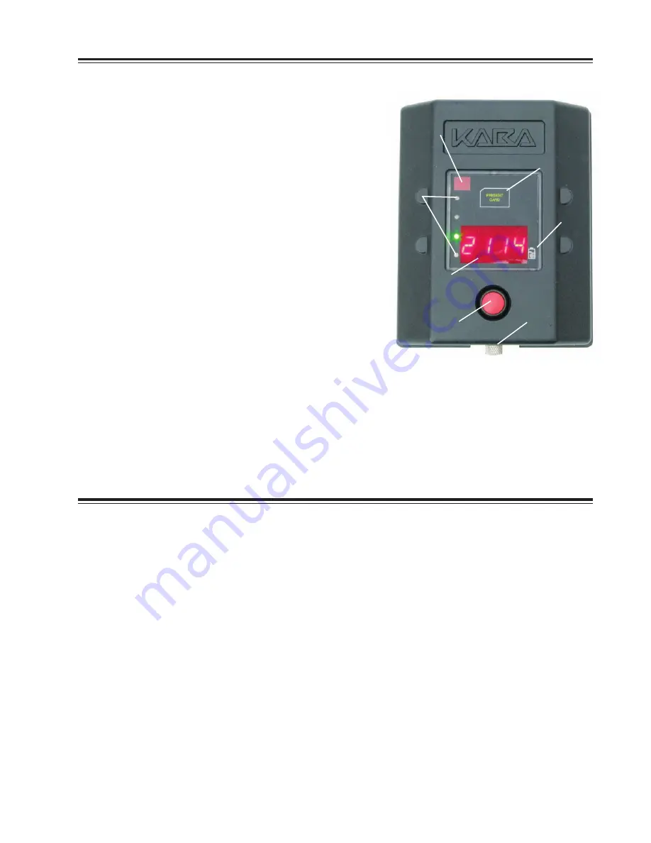
following actions. (See Figure 15 for reference.)

1.  Connect the Lock Body and input unit cable.

2.  Activate the input unit by pressing and releasing the 

RED switch button.

3.  "Open" will appear on the LED display.

4.  Insert (latch) the operating handle locking pin into the 

lock body.

5.  Press and release RED switch button.

6.  Press and release RED button again with "UNLK" 

prompt.

7.  GREEN light flashes.

8.  Present Test  Card  to  input  unit  transponder  "RFID" 

communication area.

9.  Turn dial on lock body to the left to release the handle.

10. Lift operating handle.

Operational check complete.

Battery Maintenance - Temporary Power

Replace Batteries

The four AA batteries located within the Input Unit should be replaced when the “Battery Low Indicator“ 

illuminates. To replace batteries, complete the following steps:

1.  Remove the input unit from the door (4 mounting bolts) and disconnect cable.

2.  Remove the back plate of the input unit (4 screws) and the four AA batteries in the battery retainer. 

Replace the batteries with four new high quality AA lithium batteries. Once the batteries are properly 

installed, the low battery indicator light will flash.

3.  Reattach the back plate of the input unit. 

4.  Reconnect the cable and reinstall input unit.

5.  Before closing the door, perform an operational check of the lock with the appropriate opening 

procedure as defined for the input unit.

Temporary Power

An external 9V supplementary power connector is provided to supply temporary power to the input 

unit. The 9V connector is located at the base of the input unit and is accessible by turning the 

knurled knob. It is recommended that you use a new high quality battery.

Fig. 15 - Input Unit Operation

Access to

9 volt connector

Low battery 

indicator

Transponder RFID 

communication area

IrDA

®

 port; 

Communication with 

Pocket PC/Smart Phone

LED Lights; 

Operational 

prompts and 

lock status

Switch activates 

unit and enters 

user cdes

LED displays 

seal number 

and operational 

prompts

Summary of Contents for Gitcon G-152

Page 1: ... and washers 5 Input Unit 6 Handle 6a Roll Up or 6b Swing 7 Handle Mounting Hardware Not shown in photo 8 Back Plate 8a Vertical or 8b Horizontal 9 Cable Routing Plate 9a Vertical or 9b Horizontal 10 Test card not shown Document Number 607 106 Rev B 4 08 Fig 1 Lock Body Input Unit Parts Fig 2 Vertical and Horizontal Plates Fig 3 Roll Up Handle Swing Handle 1 2 3 4 5 8a 9a 9b 8b 6a 6b ...

Page 2: ... protection Adequate protection is fitted around the surrounding area to protect such things as cables water air pipes etc from damage Before starting any work determine the position the G 152 is to be located bearing in mind the following points Ensure there is no obstruction on the inside of the door Ensure the vehicle is parked on flat level ground when installing this lock Please remember you ...

Page 3: ...oor Once the head has been ground or drilled off knock the remains of the rivet out using an appropriate sized punch Remove the handle from the door See Figure 4 Note Roll up doors will have multiple rivets that need to be removed See Figure 5 Remove Handle Retainer or Keeper Assembly 1 Drill grind the bolts out of the handle retainer assembly for swing door or the handle keeper for roll up door S...

Page 4: ...o drive the bolts into the mounting plate 6 Mount handle assembly to door and secure from the inside with washer lock washer nuts provided Note If necessary use a hacksaw to remove excess bolt length and grind any resulting sharp edges Prep Door for Lock Body 1 Using the new handle close the door s fully ensuring correct shutting for closed position 2 Align template relative to the locking pin on ...

Page 5: ...8 drill bit 6 Drill the four mounting holes for the input unit using a 10mm 3 8 drill bit Install Lock Body Input Unit Note For Roll Up Door applications using a Todco or Whiting General Purpose handle use the longer 8mm mounting bolts supplied for the bottom two holes of the lock body and use the longer 6mm mounting bolts supplied for the bottom two holes of the input unit 1 Start to attach the t...

Page 6: ...s out from the inside of the door a small amount in order to thread them into the input unit 10 Tape the cable in place in the routing channel so that it does not get pinched when the back plate is attached 11 Attach the back plate over the cable routing plate with the four remaining bolts ensuring the cable does not get pinched The cable must stay in the channel of the cable routing plate See Fig...

Page 7: ...lace batteries complete the following steps 1 Remove the input unit from the door 4 mounting bolts and disconnect cable 2 Remove the back plate of the input unit 4 screws and the four AA batteries in the battery retainer Replace the batteries with four new high qualityAAlithium batteries Once the batteries are properly installed the low battery indicator light will flash 3 Reattach the back plate ...

Page 8: ...ecure Open and close lock assembly to assure all components are properly aligned and in good operating condition Inspect physical condition of handle mounted Weather Guard and replace if needed Keep Lock Body locking jaws clean and remove any debris Apply a Dry Film Lubricant to the Lock Body locking jaws Replace Input Unit batteries at least once a year See page 7 Battery Maintenance Winter Condi...

Reviews: