10
CDX-09 Lock Assembly Template
1.
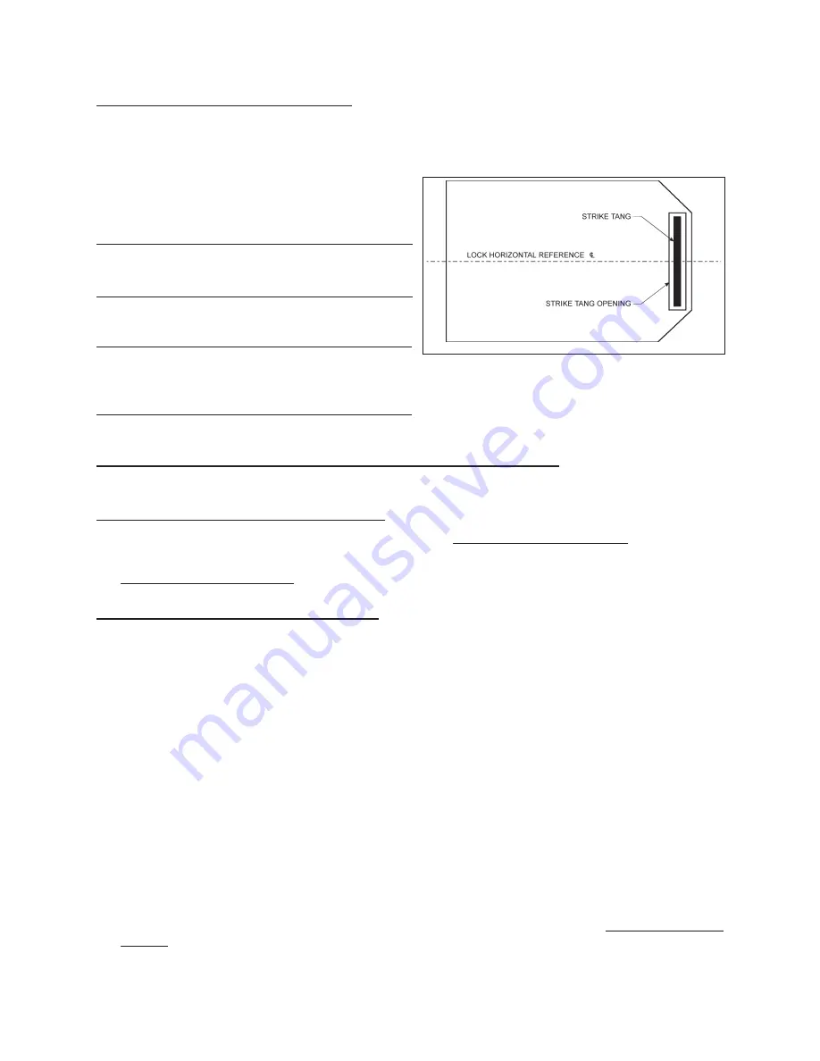
Fit the CDX-09 strike tang opening of the CDX-09 lock assembly cardboard drilling template over the strike
tang mounted on the door jamb face. Center the strike tang opening of the template horizontally over the
strike tang as shown in Figure 6.
2.
Position the lock template on the inside of the door
and align the lock horizontal reference centerline on
the lock template with the lock horizontal reference
centerline on the door. Tape the template to the door.
Note:
The door must be ajar and free to swing while
positioning the template to the strike tang and
door.
3.
Center punch all hole positions onto the inside door
surface.
Note:
It is very important to accurately center punch all
holes since hole locations establish the distance
between the Rim Exit Device and the CDX-09
lock assembly.
4.
Remove CDX-09 Lock Assembly Template and the Rim Exit Device Template.
Door Preparation for Rim Exit Device and Outside Lever Trim
1.
Using information on the Rim Exit Device template, drill holes and cut rectangular opening as directed.
Drill Holes for CDX-09 Lock Assembly
1.
Drill the 0.5 inch diameter spindle hole 1.25 inches deep. DO NOT drill through the door.
2.
Drill all six CDX-09 attaching screw holes (No. 25 drill, 0.149 inch diameter). Drill the holes 1.25 inches deep.
DO NOT drill through the door.
CDX-09 Dial Ring Mounting Template
1.
Using a square or level, transfer the lock horizontal reference centerline from the inside door surface to the
outside door surface.
2.
Establish the center of the spindle hole on the outside door surface as follows:
A. On the inside door surface measure the horizontal distance from the edge of the door to the center of
the 0.5- inch spindle hole.
B. Establish the spindle hole center on the outside door surface by measuring this distance from the
edge of the door (compensating for the door edge bevel, if necessary) along the lock horizontal
reference centerline and mark vertical centerline for 1 inch in each direction.
C. Mark horizontal line so as not to extend beyond dial ring.
3.
Center punch the hole position onto the outside of the door and drill the 0.5-inch spindle hole through the
door.
4.
Align the CDX-09 dial ring mounting template on the outside door surface with the lock horizontal reference
centerline and the 0.5-inch spindle hole. Tape the template to the door.
5.
Center punch the dial ring mounting hole positions (either the horizontal or vertical set of holes) onto the
outside of the door, and remove the template.
6.
Drill two (2) attaching screw holes (No. 29 drill, 0.136 inch diameter) 1.25 inches deep. DO NOT drill through
the door.
7.
Tap two (2) #8-32 holes, if required.
Figure 6 - CD-X09 Lock Assembly Template
Placement


