8
INSTALLATION OF THE DIAL RING
1. Remove the two screws from the dial ring assembly cover and remove
the cover.
Note:
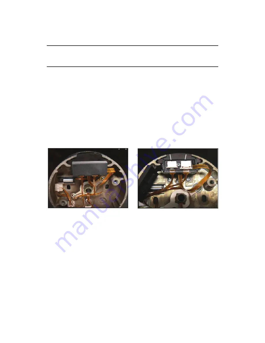
Make sure the tubes are projecting through the container as shown
in Figure 10. If not, the tubes are not seated properly in the lock or they were
not cut to the proper length. Correct the problem before proceeding.
2. If necessary, rotate the tube retainer in the dial ring so that the cables come
through the notch in the tube retainer. See Appendix A for details.
3. Feed the cables through the tube retainer on the dial ring assembly and place
the dial ring assembly over the end of the tubes. Make sure the tubes are
seated in the tube retainer on the dial ring assembly.
4. Attach the dial ring to the container with the dial ring mounting screws and
tighten to the specifi ed torque.
INSTALLATION OF THE CABLES
1. Open the ZIF (Zero Insertion Force) seal cover and move the ZIF connector
locking actuators outward to their open position. (See Figures 12 and 13.)
2. Plug the cables into the ZIF connectors with the bright metal tabs on the cables
facing toward the circuit board to which the ZIF connectors are mounted. Push
the cables into the connectors as far as they will go.
3. Close the ZIF locking actuators to lock the cables in place.
4. Close the ZIF seal cover. When closing, be sure the tenons in the seal cover
align with the holes in the coordinating piece of the seal cover.
Figure 12 - Open ZIF Seal Cover
Figure 13 - Closed & Open ZIF
Connectors
Seal Cover
ZIF Connectors
Closed
Open


