11
3. Slide the spindle through the cam
and reinsert the drive cam assembly into
the lock case and the dial ring cover until
the spindle nut is snug against the cam
and the cam is seated against the lock
case. Note that the square portion of the
spindle must be aligned with the square
hole in the lock case.
Service Tip:
If it becomes necessary to
remove and reinstall the spindle nut during
lock installation or maintenance, the drive
cam can be secured by
carefully
placing
a #1 Phillips screwdriver between the cam
and the lock case. (See Figure 20.)
4. Slide the dial hub onto the spindle,
turning the hub slightly to align the
generator drive gear teeth. Hold the drive
cam assembly in place while installing the
dial hub.
5. Snug down one setscrew to hold the dial
hub in place.
6. Mark the spindle fl ush to the dial hub.
7. Loosen the setscrew and remove the hub.
Alternate Method:
Instead of removing
the hub, you may leave it on, using the hub
as a vise to hold the spindle while cutting.
8. Carefully cut the spindle so that it will be
fl ush to the dial hub after installation.
Caution:
The spindle should not extend
past the dial hub once installed but may be
recessed up to 1/32 inch below the surface
of the hub. If it extends past the dial hub, it
must be fi led to fl ush.
9. Remove all burrs from the end of
the spindle.
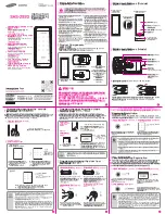
Figure 18 - Wrong Position
Figure 19 - Proper Position
Spindle fl ush to
hub or recessed
up to 1/32
"
Figure 22 - Spindle Flush
or Recessed
#1 Phillips Screwdriver
Figure 20 - Secure Drive Cam
Spindle Nut
Cam
Lock
Case
Figure 21 - Mark Spindle Flush
to Hub


