Version 02/15/2016
Page 34 of 40
Mounting instructions 82132/3xxx CB 30
13.3.2
Adjusting the keypad sub-assembly
The keypad sub-assembly has been pre-mounted in the top part of the input unit (8) as standard for the installation position
rotary handle (7) on the left, keypad on the right. If you want to maintain this installation position, this chapter can be s kipped.
However, if the input unit is to be mounted in one of the three other installation positions, the removable keypad sub-assembly
must be rotated.
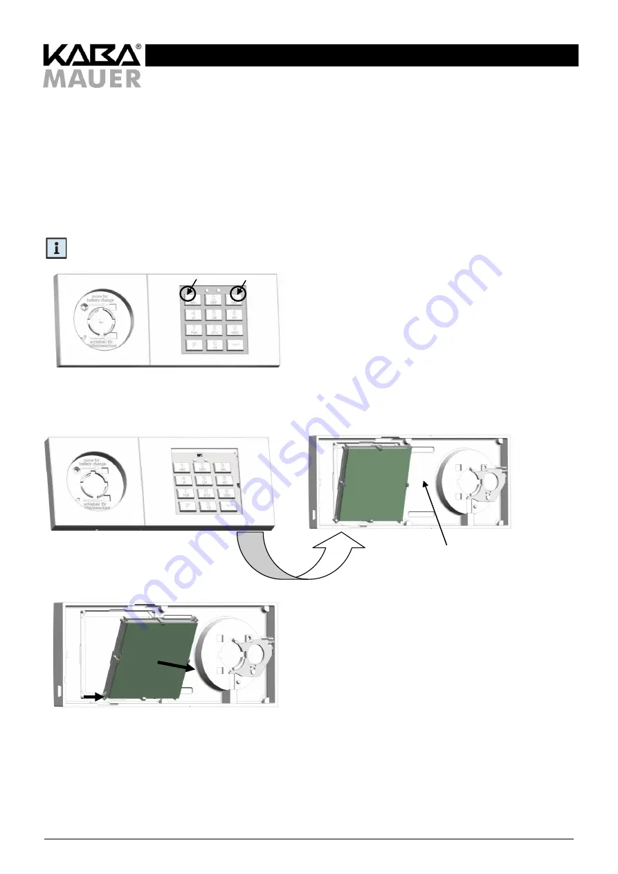
To do so, first the keypad sub-assembly must be removed from the top part of the operating unit (8). This is done by carefully
applying pressure to the areas shown in Figure 39 (do not use force or sharp-edged tools or the like). This will remove the sub-
assembly from its top holders. Next, remove the keypad unit carefully from its bottom holders (see Figures 42 and 43) and then
take it out of the top part of the operating unit (8) toward the back, if possible, without tilting or deforming the holding clamps.
Remark: Do not mount the keypad sub-assembly in other top parts, because the top parts of the input unit (8) is labled
with the product data label with the corresponding product datas of the keypad sub-assembly (see Figure 40).
Figure 39: Dismounting the keypad sub-assembly, to do so, carefully apply pressure to the upper part of the keypad
frame
Figure 40: After removing the top holder,
turn around the fitting
Figure 41: Carefully pull out the keypad sub-assembly toward the back
Now rotate the keypad sub-assembly as indicated in Table 12 and insert it again into the holders of the top part of the input unit
(see Figure 42) and press it carefully inside as far as it will go (do not apply force).
Produkt label


