Version 02/15/2016
Page 28 of 40
Mounting instructions 82132/3xxx CB 30
12 Mounting preparation
12.1
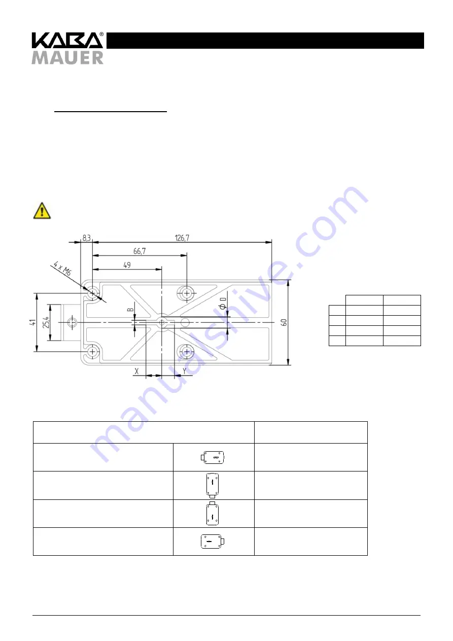
Bores and cabinet cutouts for lock
Mounting the lock (no. 1 in Figure 27) requires 4 bores with M6 thread. They must be drilled in accordance with the hole pattern
shown in Figure 28. It may be necessary for the hole pattern shown to be rotated according to Table 10 for the desired
installation position.
In addition, in order to be able to insert the inspection key and the drive shaft into the key hole, a cutout in the form of a key hole
having the dimensions and shape described in Figure 28 and Table 9 will be required. In doing so, the tolerances according to
DIN 2768-mH must be taken into account. All dimensions that are outside the data shown in Figure 28 must be coordinated
separately with certifiers (test institutes). The position of the key hole, the dimensions and the resulting required space for the
installation of the lock can be seen from Figure 28.
The following figure refers to the installation position "Bolt on the left". For other installation positions, the figure must be
rotated according to Table 10:
Table 9: Detailed dimensions
for the key hole
Figure 28: Mounting hole pattern for lock; dimensions for lock housing
here: Mounting direction bolt on the left
Mounting direction lock
Rotate Figure 28
Figure shows bolt on the left,
key hole horizontal
-
Bolt at the bottom, key hole vertical
90° counterclockwise.
Bolt at the top, key hole vertical
90° clockwise
Bolt on the right, key hole horizontal
180°
Table 10: Installation position lock, notes for Figure 28
Min. [mm] Max. [mm]
B
3.2
7.5
D
8.0
12.0
X
11.3
17.0
Y
9.0
12.5
4x M6


