Version 02/15/2016
Page 31 of 40
Mounting instructions 82132/3xxx CB 30
12.3
Drive shaft
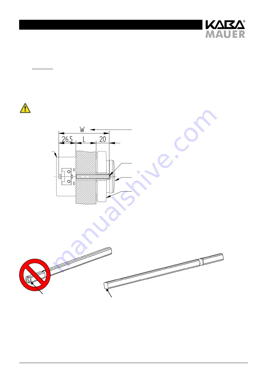
Depending on the door strength and the installation position, the drive shaft (2) included in the delivery must be adjusted to the
required functional length, in order to guarantee proper functioning of the locking system. The required length dimension W is
obtained from the distance L between the lock mounting plane and the input unit mounting plane + 20 mm immersion depth into
the input unit + 26.5 mm immersion depth into the lock (tol0/-2 mm, see Figure 32).
Shorten the drive shaft (2) only on the side
not
drilled (see Figure 33)!
To shorten it, the drive shaft (2) must be removed from the lock, since otherwise there will be a risk of damaging
the lock!
Figure 32: Required length of the drive shaft
Figure 33: Shortening the drive shaft
Shorten this side!
Do NOT shorten
this side!
[Geben Sie ein Zitat aus dem Dokument oder
die Zusammenfassung eines interessanten
Punkts ein. Sie können das Textfeld an einer
beliebigen Stelle im Dokument positionieren.
Verwenden
Sie
die
Registerkarte
'Zeichentools', wenn Sie das Format des
Textfelds 'Textzitat' ändern möchten.]
Lock (1)
Length dimension of shaft
W= 46,5 -> 46.5
Drive shaft (2)
Rotary knob (7)
Input unit (8+11)


