Version 02/15/2016
Page 38 of 40
Mounting instructions 82132/3xxx CB 30
13.3.6
Mounting the input unit top part
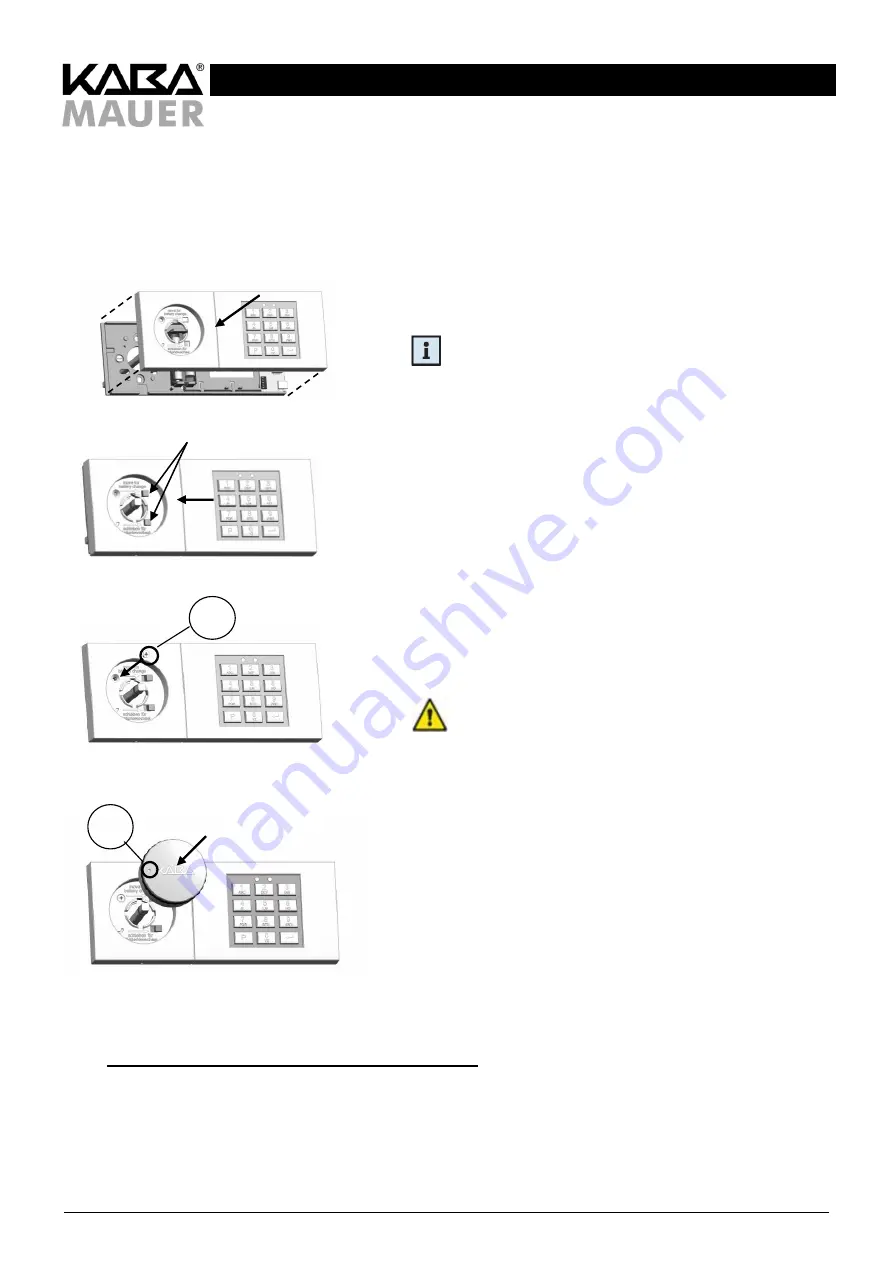
The top part of the input unit (8) is now mounted on the base part (11) as follows:
Figure 45: Inserting the top part
Place the top part (8) of the input unit carefully on the base part (11)
until the red LED lights up.
Remark: The detent lugs of the base part (11) must pass
cleanly through the top part (8) (see also Figure 46)!
Figure 46: Moving the top part
Press lightly on the top part (8) of the input unit until the detent lugs
pass completely through the base part (11) and then move the top
part (8) to the left as far as it will go until the red LED goes out.
Figure 47: Screwing down the top part
Screw the locating screw (6) with a maximum torque of 0,5 Nm
carefully into the base part (11).
Notice:
do not overtighten the screw (6).
Figure 48: Mounting the rotary handle
Check the O-ring (3) seat once again (5 - 8 mm from the front edge
of the shaft). Then insert the rotary handle (7) and lock it into place.
In doing so, make sure that in the locked state of the lock (1) the
"KABA" logo or the opening indication (15; small depression)
is horizontal.
Should the rotary handle (7) not lock into place, do not apply force,
but check the length of the shaft, the correct seat of the screws
(6 + 9) and of the O-ring and the correct seat of the top part (8) of the
input unit.
13.4
Checking/performing the mounting/adjustment procedure
After being mounted, the lock (1) and input unit (8 + 11) must be adjusted such that the rotary handle (7) can be easily rotated
and the spring force is sufficient to take the rotary handle (7) back to the zero position after a slight clockwise rotation. Should
such an adjustment not be possible, check whether the fastening holes have been drilled correctly as specified (see chapter
12.1). Should the holes not have been drilled as specified, they must be corrected.
15
Detent lugs
6


