Section 3 - 2
K
e
y
C
u
tt
in
g
&
P
in
n
in
g
Installing Blocking Pins, Discs and Fillers – Conventional Cylinders
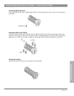
Inserting Blocking Pins
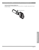
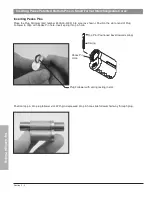
Insert two blocking pins (part number 5800-00-4010) into the blocking pin holes at the rear of the plug on
both sides.
Blocking pin
Global Assembly
Insert the plug into the housing or cylinder for final assembly.
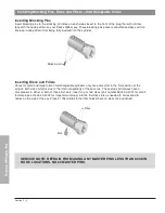
Inserting Discs and Fillers
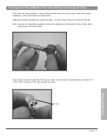
Insert discs (part number 5400-00-4002) into the Global plug disc slots that correspond with each node
position on both sides of the key. Orient discs with tabs toward the bottom of the plug. Place appropriate
filler plates in the filler holes where no discs are positioned. (Note that the filler plates are concave.)
Discs
Fillers
Summary of Contents for 5140 Series
Page 1: ...Technical Manual ...
Page 5: ...Technical Manual Section 1 Introduction ...
Page 11: ...Technical Manual Section 2 Product Information ...
Page 38: ...Section 2 27 Product Information Peaks Global Notes ...
Page 39: ...Technical Manual Section 3 Key Cutting and Pinning ...
Page 62: ...Section 3 23 Key Cutting Pinning Peaks Global Notes ...
Page 63: ...Technical Manual Section 4 Key Control Record Keeping ...
Page 73: ...Technical Manual Section 5 Cylinder Installation Guide ...
Page 84: ...Section 5 11 Cylinder Installation Guide Peaks Global Notes ...
Page 85: ...Section 5 12 Cylinder Installation Guide Peaks Global Notes ...


