background image

4

5

Lista de verificación

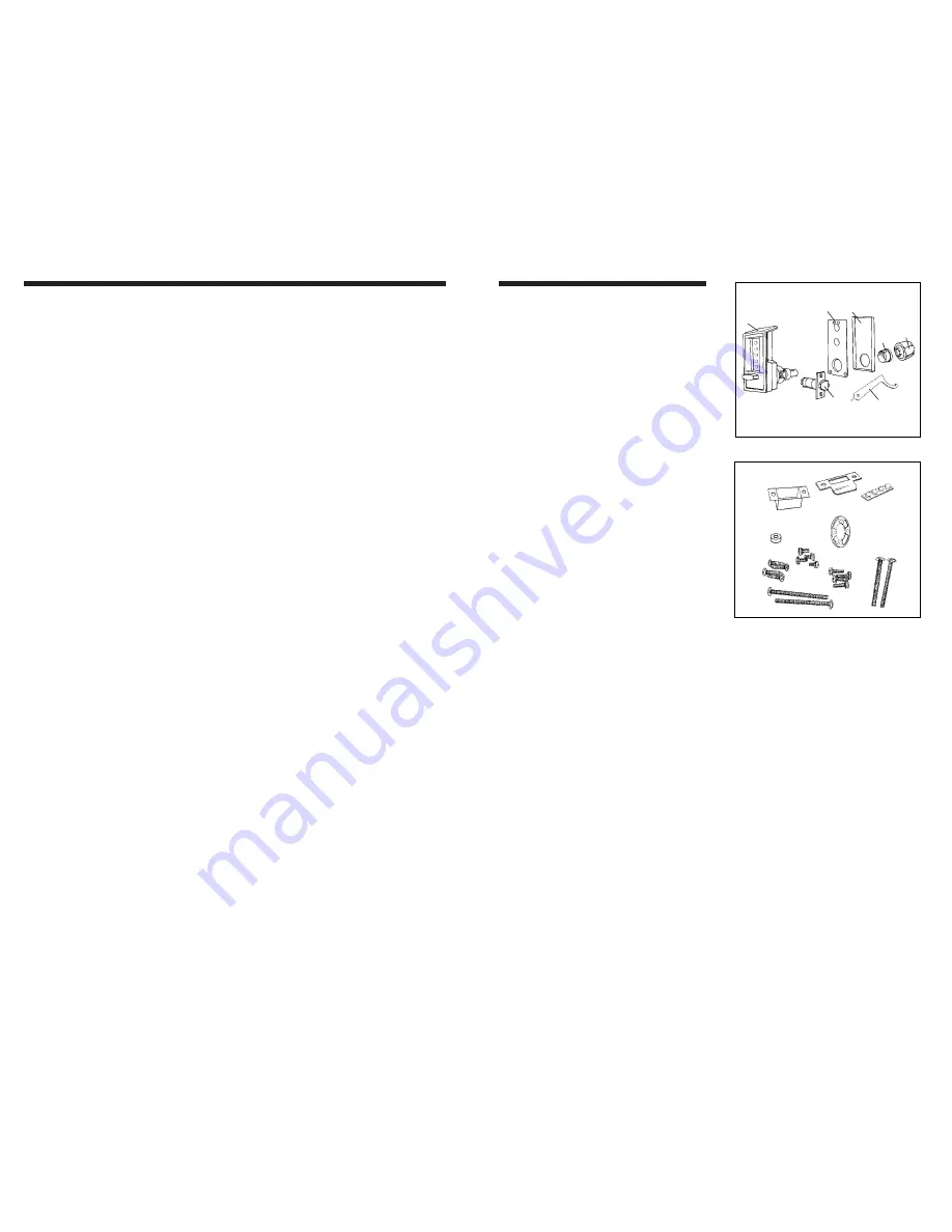
Each 6200 Series lockset includes:

A) Front lock housing assembly

B) Reinforcing plate

C) Inside trim plate

D) Thread ring

E) Inside knob

F) Deadlocking Latch

G) Spanner Wrench

Screw/accessory pack:
a) strike box
b) strike plate 
c)  drive hub spacer
d) extra spacer
e)  (4) rubber bumpers
f)  (4) 8-32 x 

3

4

" (19 mm) Phillips 

combination screws 
(for latch and strike)

g)  (4) 8-32 x 

3

16

" (5 mm) Phillips screws 

(for cylindrical drive unit)

h)  (4) 8-32 x 

11

16

" (17 mm) Phillips

screws (for cylindrical drive unit)

i) (2) 2

5

8

" (67 mm) mounting 

screws (for lock) 

j)  (2) 2" (51 mm) mounting 

screws (for lock) 

Warranty Card

Template (in center of this booklet)

Tools required:

Electric drill (variable speed)

Phillips screwdriver

Hammer

Awl or center punch

5

16

" (8 mm) drill bit

1" (25 mm) hole saw 
for Model 6204

7

8

" (22 mm) hole saw 

for Models 6214 and 6218

2

1

8

" (54 mm) hole saw 

for new door installations only

1" (25 mm) wood chisel

Cada cerradura de la Serie 6200

incluye :

A)

Caja delantera de la cerradura

B)

Placa de refuerzo

C)

Placa interior

D)

Aro roscado

E)

Pomo interior

F)

Pestillo

G)

Llave de arco

Juego de tornillos / accesorios:

a)

Caja del cerradero

b)

Placa del cerradero

c)

Espaciador del casquillo de 

accionamiento

d)

2 espaciadores adicionales

e)

4 topes de caucho

f)

4 tornillos Phillips de combinación, 

8-32 x 19 mm (

3

4

") (para pestillo y 

cerradero)

g)

4 tornillos Phillips, 8-32 x 5 mm 

(

3

16

") (para la unidad cilíndrica de 

accionamiento)

h)

4 tornillos Phillips, 8-32 x 17 mm 

(

11

16

") (para la unidad cilíndrica 

de accionamiento)

i)

2 tornillos de montaje de 67 mm 

(2

5

8

") (para la cerradura)

j)

2 tornillos de montaje de 51 mm 

(2") (para la cerradura)

Tarjeta de garantía

Plantilla (en el centro del folleto)

Herramientas necesarias:

Taladro eléctrico (de velocidad variable)

Destornillador para tornillo Phillips

Martillo

Punzón o punzón centrador

Broca de 8 mm (

5

16

")

Sierra de perforación de 25 mm (1") 

para el modelo 6204

Sierra de perforación de 22 mm (

7

8

") 

para los modelos 6214 y 6218

Sierra de perforación de 54 mm (2

1

8

") 

para la instalación de nuevas puertas 

solamente

Formón para madera de 25 mm (1")

Checklist

Chacune des serrures des séries

6200 comprend :

A) Coffre extérieur de la serrure

B) Plaque d’ancrage

C) Plaque de garniture intérieure

D) Bague filetée

E) Bouton intérieur

F) Pêne demi-tour à cran d’arrêt

G) Clé à ergots

Paquet de vis et d’accessoires :
a)

boîtier de gâche

b)

gâche 

c)

entretoise du moyeu d’entraînement

d)

entretoises supplémentaire

e)

butées de caoutchouc (4) 

f)

Vis Phillips 8-32 à tête combinée de
19 mm (

3

4

") (pour pêne et gâche) (4)

g)

Vis Phillips 8-32 de 5 mm (

3

16

") 

(pour l’unité d’entraînement 
cylindrique) (4)

h)

Vis Phillips 8-32 de 17 mm (

11

16

") 

(pour l’unité d’entraînement 
cylindrique) (4)

i)

Vis de montage de 67 mm (2

5

8

") 

(pour la serrure) (2)

j)

Vis de montage de 51 mm (2”) 
(pour la serrure) (2)

Carte de garantie

Gabarit (centre du livret)

Outils requis :

Perceuse électrique (à vitesse variable)

Tournevis Phillips

Marteau

Poinçon ou pointeau

Foret de 8 mm 

5

16

"

Scie-cloche de 25 mm (1

"

) pour le 

modèle 6204

Scie-cloche de 22 mm (

7

8

") pour les 

modèles 6214 et 6218

Scie-cloche de 54 mm (2

7

8

") 

seulement pour les nouvelles portes

Ciseau à bois de 25 mm (1”)

Liste de vérification

A

B

a

c

d

f

h

i

b

e

C

D

E

F

j

g

G

Summary of Contents for 6204 series

Page 1: ...eriod of three 3 year from date of purchase However this warranty does not cover problems arising out of improper installation or use Our only liability whether in tort or in contract under this warranty is to repair or replace products which are returned to the KABA Access Control factory shipping charges prepaid to the address shown within the three 3 year warranty period Our warranty shall only...

Page 2: ... siga cuidadosamente todas las instrucciones Dado que es muy importante instalar correctamente la cerradura verifique meticulosamente las ventanas el marco la puerta etcétera para asegurarse de que no se dañen con el método recomendado Kaba Access Control no se hace respons able de ningún daño causado por la insta ÉTAPE PAGE Liste de vérification 5 1 Vérification de la porte Inversion de la main d...

Page 3: ...onamiento i 2 tornillos de montaje de 67 mm 25 8 para la cerradura j 2 tornillos de montaje de 51 mm 2 para la cerradura Tarjeta de garantía Plantilla en el centro del folleto Herramientas necesarias Taladro eléctrico de velocidad variable Destornillador para tornillo Phillips Martillo Punzón o punzón centrador Broca de 8 mm 5 16 Sierra de perforación de 25 mm 1 para el modelo 6204 Sierra de perfo...

Page 4: ... 1 2 RH Right hand door Door opens inward push Hinged on the right side LH Left hand door Door opens inward push Hinged on the left side RHR Right hand reverse bevel door Door opens outward pull Hinged on the right side LHR Left hand reverse bevel door Door opens outward pull Hinged on the left side Thickness Measure the thickness of the door on the edge of the door A See figure 1 3 Backset Backse...

Page 5: ...r children to operate the lock To avoid interference with existing door hardware such as an auxiliary lock A see figure 1 4 Important A clearance of 4 1 2 11 cm is required above the center of the 2 1 8 54 mm hole for a normal installation whereas only 1 3 4 44 mm is needed for an inverted installation When inverting the lock the following installation changes must be done Reverse the hand of the ...

Page 6: ...the paper template found in the center of this booklet on the broken line as indicated 3 Tape the template securely to the out side of the door so that all the indicated folds are properly aligned with the high beveled edge of the door See figure 2 1 If there are existing holes in the door align the template to these holes allow ing for the proper backset measure ment Caution When a frame has an e...

Page 7: ...e speed gradually until the tip of the drill bit emerges from the other side of the door Repeat this procedure from the other side of the door This technique will prevent cracking the door or breaking the drill bit 2 If this is a new door installation use the 21 8 54 mm hole saw with a pilot drill bit to drill the hole marked B If there was a previous lock on the door this step is not necessary 3 ...

Page 8: ...u ra 4 3 4 Fije la placa de recubrimiento del pestil lo con dos de los tornillos Phillips de combinación de 8 32 x 19 mm 3 4 pro vistos artículo f en la lista de verifi cación Advertencia No cierre la puerta 4 Ajuste de la cerradura Adjusting the lock 5 This lock is factory assembled for standard doors 1 5 8 41 mm to 2 50 mm thick For doors 13 8 35 mm and 21 4 57 mm thick adjust the lock as follow...

Page 9: ...idad cilíndrica de arrastre vea la figura 5 3 4 Si necesita cambiar la dirección de apertura de la cerradura vaya a Cambio de la dirección de apertura en la página 20 antes de volver a montar la unidad cilíndrica de arrastre 5 Vuelva a montar la unidad cilíndrica de arrastre en el conjunto de la placa trasera utilizando los tornillos cortos de 5 mm 8 32 x 3 16 elemento g de la lista de comprobació...

Page 10: ...o de la placa trasera J Vea la figura 5 5 4 Vuelva a montar la unidad cilíndrica de arrastre I en el conjunto de la placa trasera J utilizando los cuatro tornillos SEM Philips de 17 mm 8 32 x 11 16 facilitados elemento H de la lista de comprobación 5 Saque provisionalmente el casquillo de arrastre F del eje de la cámara En la parte superior del espaciador del casquillo de arrastre existente G añad...

Page 11: ...em ble the cylindrical drive unit 4 Reassemble the cylindrical drive unit onto the back plate assembly 5 Reassemble the back plate onto the front lock housing assembly 6 Test the lock to make sure that it is still working properly 6 Cambio de la dirección del movimiento de la cerradura Esta cerradura viene montada de fábrica para abrir hacia la izquierda Ver la figura 6 1 Para cambiar la dirección...

Page 12: ...ion incorrecte Aux termes de la présente garantie notre seule obligation en matière contractuelle ou en matière de responsabilité civile délictuelle a trait à la réparation ou au remplacement des produits qui ont été retournés par courrier franc de port à l usine Kaba Access Control à l adresse figurant sur le présent document pendant la période de garantie de trois 3 ans La garantie n est applica...

Page 13: ...lle façon que le logement du pêne C soit face à la direction opposée 180 voir figure 6 2 Si vous vous retrouvez à ce point ci depuis Ajustement de la serrure il faut que vous y retourniez pour remonter l unité cylindrique d entraînement 4 Remontez l unité cylindrique d entraîne ment sur le palastre 5 Remontez le palastre sur le coffre extérieur de la serrure 6 Essayez la serrure pour vous assurer ...

Page 14: ...the latch A and cylindri cal drive unit B engage each other as shown in figure 7 3 4 Hold the front lock housing assembly firmly against the surface of the door 5 Clear the combination chamber by turn ing the thumbturn to the left counter clockwise to the stop position then releasing 6 Try the factory set combination Depress buttons 2 and 4 together and release Depress button 3 then release A dist...

Page 15: ...eturn and com plete the following steps 13 Use the spanner wrench A to unscrew the thread ring B see figure 7 5 14 Place the inside trim plate C onto the reinforcing plate D 15 Reinsert the thread ring B onto the inside sleeve E Use the spanner wrench to tighten the ring 16 Slide the door knob onto the inside sleeve unit until contact is made with the spring loaded retaining clip see fig ure 7 6 1...

Page 16: ...de verifi cación Si es necesario dibuje el con torno del cerradero Use esta línea como guía para cortar un mínimo de 2 mm 1 16 de material o lo suficiente para que la placa del cerradero quede a ras con el marco de la puerta Advertencia Verifique el fun cionamiento del pestillo al quedar la puer ta cerrada asegurándose de que el pin de seguridad del mismo queda detenido por la placa del cerradero ...

Page 17: ...e arco B en el agujero de cam bio de combinación como se muestra en la figura 9 2 5 Muévala hacia arriba suavemente hasta que oiga o sienta un ligero chasquido No la fuerce 6 Quite la llave de arco 7 Gire la palometa exterior hacia la izquierda hasta el tope y después suel tela para anular la vieja combinación 8 Escoja un nuevo código y anótelo para la nueva combinación se pueden uti lizar algunos...

Page 18: ...e The thumbturn should rotate The latch will be retracted flush with the face plate The correct combination must be entered each time you want to unlock the door 15 Replace the rubber cap to cover the combination change hole 9 9 4 Changement de la combinaison Suite 10 Actionnez le tourniquet vers la droite sens des aiguilles d une montre jusqu en fin de course et maintenez le ainsi Le pêne doit se...

Page 19: ...ted by adding bumpers to the door stop Installing Rubber Bumpers provided in accessory pack item e on checklist 1 Close the door and apply pressure making sure that the dead latch rests on the strike plate 2 Standing on the door stop side of the door check for gaps between the door and the door stop on all three sides of the frame left right and top Mark locations where the gaps are approximately ...

Page 20: ...s gira el pomo no apriete los botones 1 Gire la palometa a la izquierda y suél tela para anular la combinación 2 Apriete y suelte los botones adecuados para introducir su combinación Cada vez que apriete un botón oirá un ligero chasquido 3 Gire la palometa a la derecha hasta el tope y manténgala así 4 Abra la puerta 5 Suelte la palometa Fonctionnement des serrures de la série 6200 Ne forcez jamais...

Page 21: ...nstalado en la puerta Repita las instrucciones de la sección 4 Después de introducir la nueva combi nación la cerradura sólo funciona una vez luego no abre Al cambiar la combinación los botones no se apretaron completamente Uno de los botones apretados no se registró Apriete otros botones del códi go Si esto no funciona la combi nación se ha perdido Para obtener más asistencia llame al 1 800 849 t...

Page 22: ...39 38 NOTES NOTES ...

Reviews: