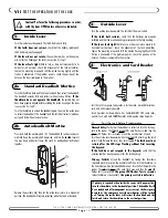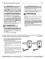
background image

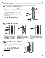
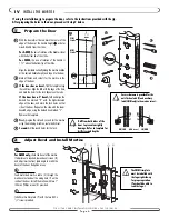
The SMM trim plate
must be installed with
the logo right-side-up
for proper operation.
(You should be able to
read the logo.)

!

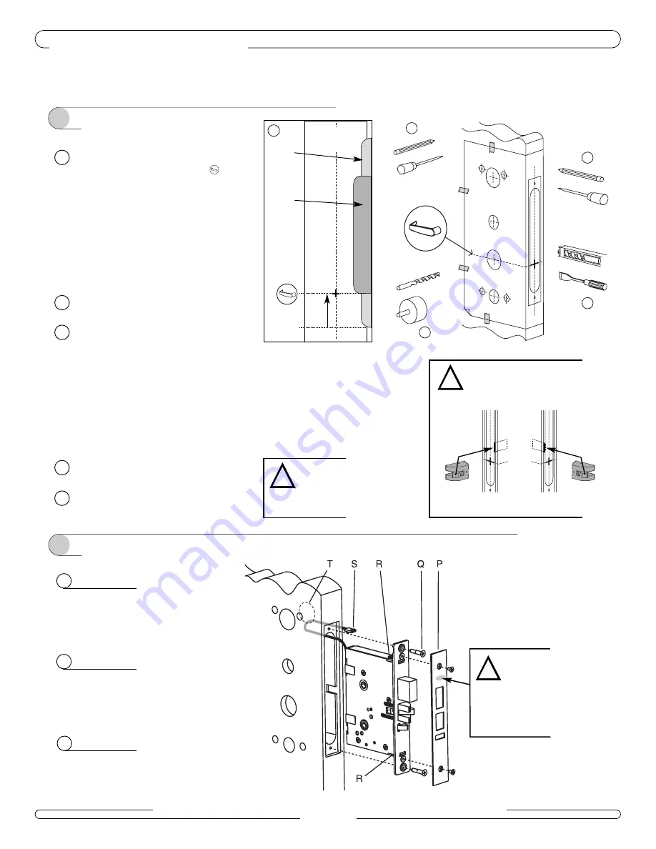
If using the installation jig to prepare the door, refer to the instructions provided with the jig. 
After preparing the holes in the door, proceed with step 2 below.

A

For AMM only,

check the bevel of the mortise.

If adjustment is required, loosen bevel screws (R),
and adjust mortise front plate angle to match the
bevel of the door. Retighten screws.

2

Adjust Bevel and Install Mortise

Align the template vertically along the mortise midline
at the desired handle height, and tape it to the door.

Mark all holes and cutouts for the mortise in the
edge of the door.

If the door has no bevel,

fold the template along

the solid lines. Align the fold with the edge of the door,
and mark the holes for the lock. Repeat on other side.

If the door has a 3º bevel, 

fold and align the

dashed line marked “H” with the higher-beveled
edge of the door, and mark the lock holes on that
side of the door. Repeat on the side with the lower-
beveled edge, using the dashed line marked “L”.

Remove the template.

First,

prepare the slot and cut-outs for the mortise

using the mortising machine, router and chisel.

Second,

drill the round holes for the lock.

Drill from both sides of the
door to prevent unsightly
damage. Refer to template for
drill sizes and depths.

!

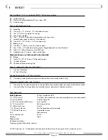
1

Prepare the Door

B

C

D

E

B

E

D

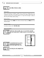
With the door almost closed, mark the center of the
edge of the door at the handle height 

as deter-

mined directly from the strike: 

For AMM

, the axis of rotation of the handle is level

with the bottom lip of the strike.

For SMM,

the axis of rotation of the handle is

1

1

/

4

” above the bottom lip of the strike.

I V

INSTALL THE MORTISE

7 1 0 - I I / 7 4 0   S E R I E S   I N S TA L L AT I O N   G U I D E   •   P K 2 7 1 0 / 0 8 / 0 2

P a g e   6

A

A

ESM
Strike

(ESM)

ASM
Strike

1

1

/4”

C

!

Ensure clearance is provided for the
anti-friction latch (F) and auxiliary
latch (SMM only) in the mortise cutout:

RH/LHR    

(AMM shown)

LH/RHR

Door

(

C L

)

F

F

B

Feed motorized mortise cable (S) through the
mortise cutout and out the wiring hole (T) on the
inside of the door. Install the mortise with two 1”
(25mm) Phillips screws (Q) provided. 

C

Install mortise trim plate (P) with the two 8-32 x

1

/

4

” screws provided. 

Summary of Contents for AADB

Page 1: ...INSTALLATION GUIDE Solitaire 710 II and SMART 740 Series AMM and AADB Models PK2710 T ...

Page 2: ...ilpiece retaining clip Tools in spare parts box not illustrated 5 64 hex Allen key 1 8 hex Allen key Packaged separately with lock shipment T Override cylinder mechanical core and removable core override models only Shipped separately after lock shipment One entry key for mechanical core and removable core override models per order of identical cylinders One control key for removable core override...

Page 3: ...710 II 740 SERIES INSTALLATION GUIDE PK2710 08 02 Page 3 A D E K T H I Q J K B G B1 B2 F G P O P F C R N M L S ...

Page 4: ...zed Mortise Technical Assistance For technical assistance call 1 800 906 4526 Warnings and Cautions II INTRODUCTION AND DISCLAIMERS 710 II 740 SERIES INSTALLATION GUIDE PK2710 08 02 Page 4 Please read and follow all directions carefully Important Carefully inspect windows doorframe door etc to ensure that the recommended procedures will not cause damage Kaba Ilco s standard warranty does not cover...

Page 5: ...x optional for wood door frames required for metal door frames and check the strike handing on the template Install the strike using the screws provided 1 Mark the Location of the Strike 2 Prepare the Doorframe A Mortise the doorframe to receive the dust box and drill the pilot holes for the mounting screws dimensions and depths marked on template B Position the strike against the doorframe and al...

Page 6: ...r Repeat on the side with the lower beveled edge using the dashed line marked L Remove the template First prepare the slot and cut outs for the mortise using the mortising machine router and chisel Second drill the round holes for the lock Drill from both sides of the door to prevent unsightly damage Refer to template for drill sizes and depths 1 Prepare the Door B C D E B E D With the door almost...

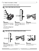
Page 7: ...e of the door Mark the tail piece accordingly V PREPARE THE MECHANICAL OVERRIDE 710 II 740 SERIES INSTALLATION GUIDE PK2710 08 02 Page 7 2 Removable Core Cylinder Mechanical Override 1 Key in Knob Mechanical Override If you have an electrical override lock continue on page 8 A Hold the outside housing against the door The tailpiece should extend between 1 4 and 5 8 beyond the rear face of the door...

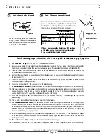
Page 8: ...ews Q on the bottom right and top left of the inside housing 12 Turn the outside lever and then the inside lever to ensure that the bolt retracts 13 For mechanical override models the override key has been sent to the manager Test the override in the manager s pres ence Turn the key 2 3 of a rotation clockwise for a left hand lock and counterclockwise for a right hand lock The cylinder and the ins...

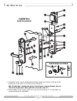
Page 9: ...ontinuously Reset the electronics by disconnecting the battery pack for ten seconds then reconnect it 18 Install the medallion A on the outside housing and secure it using the 5 64 hex head screw C On electrical models tuck electrical override terminals B inside medallion 710 II 740 SERIES INSTALLATION GUIDE PK2710 08 02 Page 9 VI INSTALL THE LOCK A X1 X2 B C D U H E I J K L M N S P O Q Q V W D E ...

Page 10: ...handing If the lever feels tight hard to turn or does not return easily to its horizontal rest position check the alignment of the lock assemblies Loosen the mounting screws and shift the outside housing slightly until the friction is eliminated If the problem persists check the position of the holes on the door compared to the mortise Test the lock s response to keycards a Test keycard a Grand Ma...

Page 11: ...o extend the deadbolt On autodeadbolt models the dead bolt should have extended when the door was closed Open the door by turning the lever The deadbolt and the latch bolt retract simultaneously and fully Take note of any excess friction which might necessitate filing the strike deadbolt area only Repeat Remove the lock batteries and unsnap the battery wire connector from the battery pack Remove t...

Page 12: ...ontréal QC H4P 2G7 Technical Support 1 800 906 4526 Customer Service T 1 877 468 3555 F 514 735 6589 General Information www kabalodging com Online Consumable Orders www keycard com To access all of our easy steps please visit our Support Website http connect kabalodging com ...

Reviews: