background image

DE/EN/FR/IT

BEYOND SECURITY

Kaba c-lever acc. EN1906 Cl.1

Kurzanleitung
Quick Guide
Notice succincte
Istruzioni brevi

Doc.-No.: k2evo705xy-2013-09

Summary of Contents for c-lever acc. EN1906 Cl.1

Page 1: ...DE EN FR IT BEYOND SECURITY Kaba c lever acc EN1906 Cl 1 Kurzanleitung Quick Guide Notice succincte Istruzioni brevi Doc No k2evo705xy 2013 09 ...

Page 2: ...D www kaba at www kaba de www kaba ch Kaba Ltd Kaba S A S Kaba S r l Lower Moor Way Business Park 9 rue Pagès Via Andrea Costa 6 Tiverton Devon 92150 Suresnes 40013 Castell Maggiore BO EX 16 6SS FRANCE ITALY ENGLAND www kaba co uk www kaba fr www kaba it This documentation may not be reproduced in any way nor further used in other ways without written permission of Kaba AG Kaba and Kaba elolegic a...

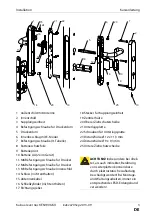
Page 3: ...ube Innenschild 14 Schloss nicht enthalten 15 Antennenkabel 16 Schließzylinder nicht enthalten 17 Richtungsgeber 18 Stecker für Kupplungseinheit 19 Zentrierhülse 20 Oberer Ziehschutzscheibe 21 Unterlagsplatte 22 Schrauben für Unterlagsplatte 23 Distanzhülse Ø 12 x 11 3 mm 24 Distanzhülse Ø 9 x 9 3 mm 25 Untere Ziehschutzscheibe 1 15 24 21 22 18 11 3 4 5 6 20 7 2 14 16 12 25 13 8 10 9 23 19 ACHTUNG...

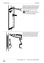
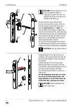
Page 4: ...hablone auf den Drückerdorn aufstecken Nach Ausrichten der Schab lone die Befestigungslöcher markieren HINWEIS Bei einigen Drücker formen ist der Drückerdorn 5 an die Türstärke anzupassen Schloss entfernen und die bereits ange zeichneten Befestigungslöcher bohren Nach dem Bohren die Späne entfernen und das Schloss 14 wieder montieren ...

Page 5: ...chten Tür der Vierkant der Kupplungseinheit 3 gegen den Uhrzeigersinn und bei einer linken Tür im Uhrzeiger sinn bis auf Anschlag gedreht wer den Die Kupplungseinheit 3 mit dem oberen Teil voran in das Außenschild 1 schieben Danach den unteren Teil der Kupplungs einheit 3 unter Hilfenahme eines Schrau bendrehers ebenfalls in das Außenschild 1 schieben Die Kupplungseinheit muß fest und eben im Auße...

Page 6: ...dorn 5 in Pfeilrichtung angezogen werden HINWEIS Antennenkabel 15 nicht quetschen HINWEIS Beim Drückerdorn 7 mm muss die Reduzierhülse so eingebaut werden dass die Frei stellung der Hülse nach oben zur Stiftschraube 4 zeigt Den Drückerdorn 5 entsprechend Schlossnuss auswählen und in den Vier kant der Kupplungseinheit 3 stecken danach Drückerdorn von oben mit Gewindestift 4 befestigen Kupplungs ein...

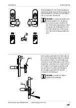
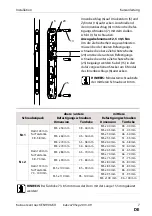
Page 7: ... 75 mm 71 75 mm M5 x 80 mm 76 80 mm M5 x 100 mm 85 94 mm M5 x 85 mm 81 85 mm M5 x 90 mm 86 90 mm M5 x 110 mm 95 100 mm M5 x 95 mm 91 95 mm M5 x 100 mm 96 100 mm Innenbeschlag 6 auf Drückerdorn 5 und Zylinder 16 aufstecken Anschließend den Innenbeschlag 6 mit den drei Befes tigungsschrauben 7 mit dem Außen schild 1 festschrauben Anzugsdrehmoment 2 5 0 5 Nm Um die Ziehsicherheit zu gewährleisten müs...

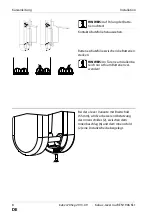
Page 8: ... mm wird zur besseren Abstützung des Innenschildes 2 zwischen dem Innenbeschlag 6 und dem Innenschild 2 eine Distanzscheibe beigelegt HINWEIS Auf Polung der Batte rien achten Kontaktschutzfolie herausziehen Batterieschutzfolie zwischen die Batterien stecken HINWEIS An Türen zum Außenbe reich nur Lithium Batterien ver wenden ...

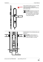
Page 9: ...efestigen HINWEIS Zylinderüberstand innen mindestens 18 5 mm und aussen mindestens 23 5mm Innenschild 2 aufstecken und von unten mit M3 Schraube 13 befestigen Zuletzt M6 Stiftschraube 12 in den Drü cker einschrauben HINWEIS Batterietausch Die M3 unten Schraube 13 entfernen Schraubendreher in die Senkung der Schraube einführen und das Innenschild anheben ...

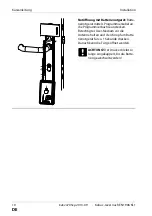
Page 10: ...rät Batte rienotgerät mittels Programmierkabel an die Programmierbuchse anstecken Berechtigtes User Medium vor die Antenne halten und den Knopf am Batte rienotgerät für ca 1 Sekunde drücken Danach kann die Tür geöffnet werden ACHTUNG Der Drücker bleibt so lange eingekuppelt bis die Batte rien gewechselt werden ...

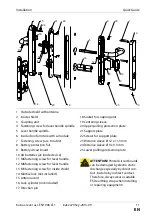
Page 11: ...3 fastening screw for inside shield 14 Mortise lock not included 15 Antenna cord 16 Lock cylinder not included 17 Direction pin 18 Socket for coupling unit 19 Centering sleeve 20 Upper pulling protection plate 21 Support plate 22 Screws for support plate 23 Distance sleeve Ø 12 x 11 3 mm 24 Distance sleeve Ø 9 x 9 3 mm 25 Lower pulling protection plate 1 15 24 21 22 18 11 3 4 5 6 20 7 2 14 16 12 2...

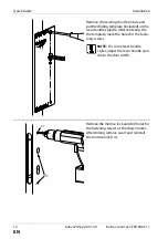
Page 12: ...e included on the lever handle spindle After centering the the template mark the holes for the faste ning screws NOTE For some lever handle styles adjust the lever handle spin dle to the door width Remove the mortise lock and drill holes for the fastening screws at the drawn marks After drilling remove swarf and reinstall the mortise lock 14 ...

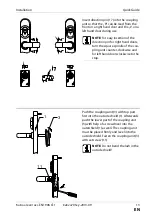
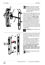
Page 13: ... for right hand doors turn the square spindle of the cou pling unit counter clockwise and for left hand doors clockwise to the stop Push the coupling unit 3 with top part first into the outside shield 1 Afterwards push the lower part of the coupling unit 3 with help of a screwdriver into the outershield 1 as well The coupling unit must be placed firmly and level into the outside shield Fasten the ...

Page 14: ... putting the outside shield on the door NOTE Do not pinch the antenna cord 15 NOTE For a spindle of 7 mm the reduction sleeve must be fitted such that the release for the sleeve is pointing upwards towards the fixing screw 4 Select the lever handle spindle 5 accord ing to the mortise lock follower and insert into the square of the coupling unit 3 see figure afterwards handle spindle fasten from ab...

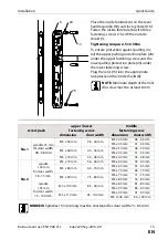
Page 15: ... mm 75 84 mm M5 x 75 mm 71 75 mm M5 x 80 mm 76 80 mm M5 x 100 mm 85 94 mm M5 x 85 mm 81 85 mm M5 x 90 mm 86 90 mm M5 x 110 mm 95 100 mm M5 x 95 mm 91 95 mm M5 x 100 mm 96 100 mm Place the inside furniture 6 on the lever handle spindle 59 and lock cylinder 16 Fasten the inside furniture 6 with three fastening screws 7 with the outside shield 1 Tightening torque 2 5 0 5 Nm To ensure protection again...

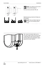
Page 16: ...e sleeve which is placed between the inside door furni ture 6 and the inside shield 2 to better support the inside shield 2 NOTE Pay attention to the correct position of the batteries Pull the contact protection film out Slide the battery protection foil between the batteries NOTE Only use lithium batteries on doors in an outside environ ment ...

Page 17: ...stening screw NOTE Cylinder stand off on the inside 18 5 mm minimum and the outside 23 5 mm minimum Snap on the inside shield 2 and fasten with an M3 screw 13 from below Finally screw the M6 set screw 12 in the lever handle NOTE Replacing the batteries Remove the lower M3 screw put the screwdriver in the screw coun ter sink and lift off the inside shield 2 ...

Page 18: ...e Plug the emer gency battery device with the program ming cord to the programming receptacle Hold a valid user medium in front of the antenna and press the button on the emergency opening device for about 1 second Afterwards the door can be ope ned ATTENTION The lever handle remains engaged until the batter ies have been replaced ...

Page 19: ...pour garniture intéri eure 14 Serrure non fournie 15 Câble d antenne 16 Cylindre non fournie 17 Distributeur de direction 18 Prise pour module d accouplement 19 Douille de centrage 20 Discques de anti arrachement supérieur 21 Plaque d assise 22 Vis pour plaque d assise 23 Douille d ecartement Ø 12 x 11 3 mm 24 Douille d ecartement Ø 9 x 9 3 mm 25 Discques de anti arrachement inférieur 1 15 24 21 2...

Page 20: ...ourni sur la broche de poignée Après voir positionné le gabarit marquer l emplacement des trous de fixation NOTE Pour certaines formes de poignées adapter la broche de poignée 5 à l épaisseur de la porte Retirer la serrure et percer les trous de fixa tion aux emplacements marqués Retirer les copeaux de perçage et remonter la ser rure 14 ...

Page 21: ...ment 3 doit être tourné dans le sens des aiguilles d une montre pour une porte à main droite et pour une porte à main à gauche dans le sens inverse des aiguilles d une montre Glisser le module d accouplement 3 dans la garniture extérieure 1 avec la partie supérieure vers l avant Glisser ensuite la partie inférieure du module d accouple ment 3 dans la garniture extérieure 1 en s aidant d un tournev...

Page 22: ... fixé la garniture extérieure 1 HINWEIS Ne pas coincer le câble d antenne 15 NOTE Sur la broche de poignée 7 mm la douille de réduction doit être montée de manière à ce que l évidement de la douille soit ori enté vers le haut vers le goujon fileté 4 Sélectionner la broche de poignée 5 en fonction du fouillot et l enficher dans le carré du module d accouplement 3 voir croquis puis fixer par le haut...

Page 23: ...4 mm M5 x 75 mm 71 75 mm M5 x 80 mm 76 80 mm M5 x 100 mm 85 94 mm M5 x 85 mm 81 85 mm M5 x 90 mm 86 90 mm M5 x 110 mm 95 100 mm M5 x 95 mm 91 95 mm M5 x 100 mm 96 100 mm 20 13 6 25 Placer la garniture intérieure 6 sur la bro che de poignée 5 et le cylindre 16 Vis ser ensuite la garniture intérieure 6 à la garniture extérieure 1 à l aide des trois vis de fixation 7 Moment de couple de serrage 2 5 0...

Page 24: ...une rondelle d écartement est placée entre la garniture intérieure 6 et la plaque intérieure 2 afin de mieux mainte nir la plaque intérieure 2 NOTE Respecter la polarité des piles Retirer le film de protection Placer le film de protection des piles entre les deux piles NOTE pour des portes extérieures n utiliser que des piles au lithium ...

Page 25: ...s de cylindre NOTE Dépassement minimal du cylindre à l intérieur 18 5 mm à l extérieur 23 5 mm Placer la garniture intérieure 2 et fixer par le bas avec la vis M3 13 Visser ensuite le goujon fileté M6 12 dans la poignée NOTE Échange des piles retirer la vis M3 en bas placer le tourne vis dans la cuvette de la vis et rele ver la garniture intérieure ...

Page 26: ... l aide du câble de programmation raccorder l appareil d urgence sur piles à la douille de programmation Maintenir le Média Utilisateur devant l antenne et appuyer pendant env 1 seconde sur le bouton de l appareil d urgence sur piles Il est alors possible d ouvrir la porte ATTENTION La poignée reste accouplée jusqu à ce que les piles soient échangées ...

Page 27: ... Serratura non compresa 15 Cavo antenna 16 Cilindro di chiusura non compreso 17 Direzionatore 18 Spina per unità di attacco 19 Manicotto di centratura 20 Disco antiestrazione superiore 21 Piastra di appoggio 22 Vite per piastra di appoggio 23 Manicotto distanziatore Ø 12 x 11 3 mm 24 Manicotto distanziatore Ø 9 x 9 3 mm 25 Disco antiestrazione inferiore 1 15 24 21 22 18 11 3 4 5 6 20 7 2 14 16 12 ...

Page 28: ...la dima fornita nel perno quadro Una volta allineata la dima segnare i fori di fissaggio NOTA Con alcuni tipi di maniglia il perno quadro 5 deve essere adattato allo spessore della porta Rimuovere la serratura ed eseguire i fori di fissaggio precedentemente segnati Terminata la foratura rimuovere lo sfrido e rimontare la serratura 14 ...

Page 29: ...rno dell ingegno 3 deve essere girato in senso antiorario per una porta destra mentre per una porta sinistra deve essere girato in senso orario fino al punto di stop Inserire l unità di attacco 3 con la parte superiore in avanti nella placca esterna 1 Successivamente spingere la parte inferiore dell unità di attacco 3 con l ausilio di un cacciavite anche nella placca esterna 1 L unità di attacco d...

Page 30: ...cessario spingere in direzione della freccia NOTA Non schiacciare il cavo dell antenna 15 NOTA Nel caso del perno quadro da 7 mm è necessario installare il manicotto di riduttore in modo che il gioco del manicotto sia ori entato verso l alto in direzione della vite prigioniera 4 Scegliere il perno quadro 5 conformemente alla noce della serratura e inserirla nel quadrato dell unità di attacco 3 dop...

Page 31: ...90 mm 75 84 mm M5 x 75 mm 71 75 mm M5 x 80 mm 76 80 mm M5 x 100 mm 85 94 mm M5 x 85 mm 81 85 mm M5 x 90 mm 86 90 mm M5 x 110 mm 95 100 mm M5 x 95 mm 91 95 mm M5 x 100 mm 96 100 mm Applicare il ferramento interno 6 al perno quadro 5 e al cilindro 16 Infine fissare il ferramento interno 6 con le tre viti di fissaggio 7 sulla placca esterna 1 Momento torcente 2 5 0 5 Nm Per una maggiore sicurezza di ...

Page 32: ...r un migliore supporto della placca interna 2 viene utilizzato un disco distanziatore tra il ferramento interno 6 e la placca interna 2 NOTA Prestare attenzione alla polarità delle batterie Estrarre la lamina di protezione del contatto Inserire la lamina di protezione tra le batterie NOTA Per le porte da esterno utilizzare solo batterie al litio ...

Page 33: ...ite a testa cilindrica NOTA Sporgenza del cilindro interna minimo 18 5 mm ed esterna minimo 23 5 mm Applicare la placca interna 2 e fissare dal basso con una vite M3 13 Avvitare la vite prigioniera M6 12 nella maniglia NOTA Sostituzione delle batterie Rimuovere la vite 13 M3 inferiore inserire il cacciavite nella svasatura della vite e sollevare la placca interna ...

Page 34: ...gare l apparecchio di alimentazione di emergenza usando il cavo di programmazione alla boccola di programmazione Tenere il supporto utente abilitato davanti all antenna e premere il pulsante sull apparecchio di alimentazione di emergenza per circa 1 secondo La porta può essere aperta ATTENZIONE La maniglia resta accoppiata fino a che le batterie non vengono sostituite ...

Reviews: