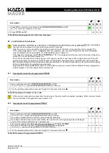
Version 2014-02-28
Page 31 of 48
Operating instructions 82132/3XXX - Combi B 30
19 Lock system: Input unit and lock
The entire lock system consists of a visible input unit and the lock installed in the secure storage unit.
All programmed codes and functions are saved only in the lock and, thus, in the secured area.
19.1
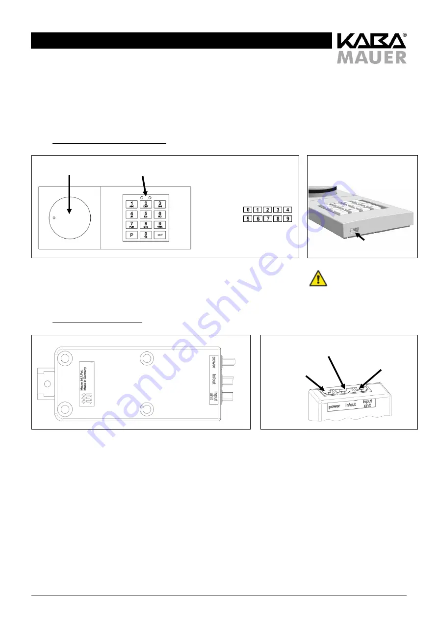
Operating elements of the input unit
Figure 9: Input unit
Figure 10: Mini-USB socket
Special interface, only in
connection with original
Kaba Mauer CB30
Use PC cable!
19.2
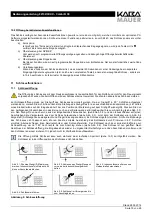
Lock housing and interfaces
Figure 11: Lock housing
Figure 12: Connections at the lock housing
Actuating knob
Keypad
Keypad:
1 red and 1 green LED
Numeric keys
P key
Enter key
Connection to the
input unit
Connection to further
components (e.g. EMA)
Power
supply

