Version 2014-02-28
Page 46 of 48
Operating instructions 82132/3xxx CB 30
28.1
Undervoltage indication
If the operator receives the undervo
must be replaced promptly (see chapter13.2).
As soon as the undervoltage indication is displayed, the lock can still be opened, but no reprogramming is possible until
after the battery replacement. Furthermore, an audit entry is performed. As soon as the battery is almost completely
exhausted, no opening can be performed and every key stroke is acknowledged with an undervoltage signal.
28.2
Battery replacement
Do not apply force and avoid touching electronic components! You could destroy the lock.
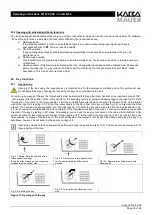
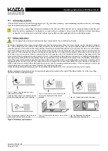
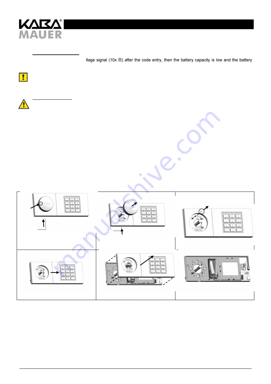
For battery replacement the rotary handle of the lock must be dismounted. Since the rotary handle can be inserted in steps of
90 ° , first, always note the position of the rotary handle for the assembly later (e.g. using an adhesive tape on the input unit to
mark the position of the mark on the rotary handle). Insert the enclosed Allen wrench up to the stop into the hole on the lateral
wall of the input unit as shown in Fig. 6.1. Pull out the rotary handle to the front from the input unit (see fig. 6.2) and remove the
Allen wrench. Then unscrew the screw in the handle recess (see fig. 6.3). After that the top part of the input unit can be moved
as shown in fig. 6.4 and then it can be removed to the front (see fig. 6.5). The 2 batteries are located on the base part of the
input unit and can be replaced now as shown in fig. 6.6. Only batteries of type AAA can be used. It is highly recommended to
use high-quality brand batteries and replace them as a precaution every 24 months at the latest. After the battery replacement
mount the input unit on the base part from the front in the order reverse to the one described above and move it laterally until it
engages and the red LED turns off. Then attach the screw to secure the top part. Now attach the rotary handle in the position in
which it has been mounted before dismounting (to do so, use the marking mentioned above). If the mounting is correct, the
rotary handle can no longer be removed. Remove the marking (in this way).
Finally, the take-off contact message must be neutralised (see chapter 9.6). It can be performed only by the master.
Battery replacement (example above: the input unit keyboard is located to the right of the rotary handle. For other mounting
positions proceed correspondingly):
Fig. 6.1: Notice: Note the position of the
rotary handle (marking).
Insert the Allen wrench into the small hole on
the bottom side and press it in to the stop.
Fig. 6.2: Remove the rotary handle to the
front, while keeping the Allen wrench
pressed.
Fig. 6.3: Loosen and remove the screw.
Fig. 6.4: Move the top part of the input unit in
the direction of the arrow to the stop.
Fig. 6.5: Remove the top part of the input unit
carefully.
Fig. 6.6: Replacing the batteries.
Mounting in the reverse order.
Figure 14: Battery replacement

