6
C. LOCK PREPARATION
C-1
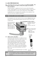
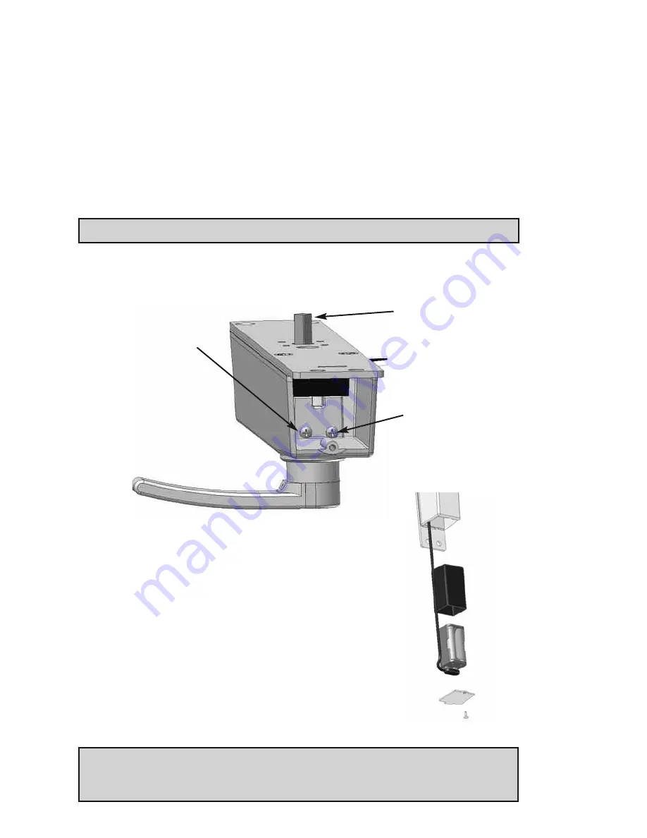
On Deadlatch Model only, remove Handing Screw
(FIG 4)
:
Caution: The
appropriate handing screw must be removed for proper lock function
after installation.
Inside the battery compartment, the lock comes with both handing
screws installed. Based on the door application handing, Left Hand (LH)
or Right Hand (RH) one screw must be removed as noted in
FIG 4
.
Deadbolt Models, are shipped with no handing screws attached. They
must be removed for Deadbolt applications.
Note:
A RH Deadlatch lock is shown in
FIG 4
.
For Deadlatch Locks only, orient the lock as shown in
FIG 4
(spindle up)
and remove the appropriate shipping screw, left screw for LH or right
screw for RH.
Figure 4
Remove left handing
screw for left hand
application.
Note:
Right Hand
application shown,
Left Hand application
would show the lever
on the opposite side.
Remove right handing
screw for right hand
application.
Note:
Right Hand
application shown.
Spindle Assembly:
Deadlatch—Upper Hole
(Deadlatch assembly
shown)
Deadbolt—Lower Hole
C-2
Battery Pack Installation
Secure the connection end of the Battery Pack to
the Cable Harness. After the connection, the lock
will set itself and you should hear an audible
sound, spinning of the inside motor, and see a
green light—all simultaneously. Upon connection,
place the Battery Pack into the rubber battery
housing, harness connection up, and slide the
assembly into the battery compartment
(see Fig
5)
. Secure in place with the Battery Cover and
Torx Screw.
The lock can now be programmed prior to installa-
tion if desired.
Figure 5
Note:
If your application requires a change of cylinder, that step should
be done at this time, before installation. If not required, skip to
section D.
Summary of Contents for E-PLEX 3X00 SERIES
Page 1: ...INSTALLATION INSTRUCTIONS E PLEX 3X00 SERIES NARROW STILE LOCK ...
Page 9: ...9 Notes ...
Page 10: ...10 Notes ...


