4
5
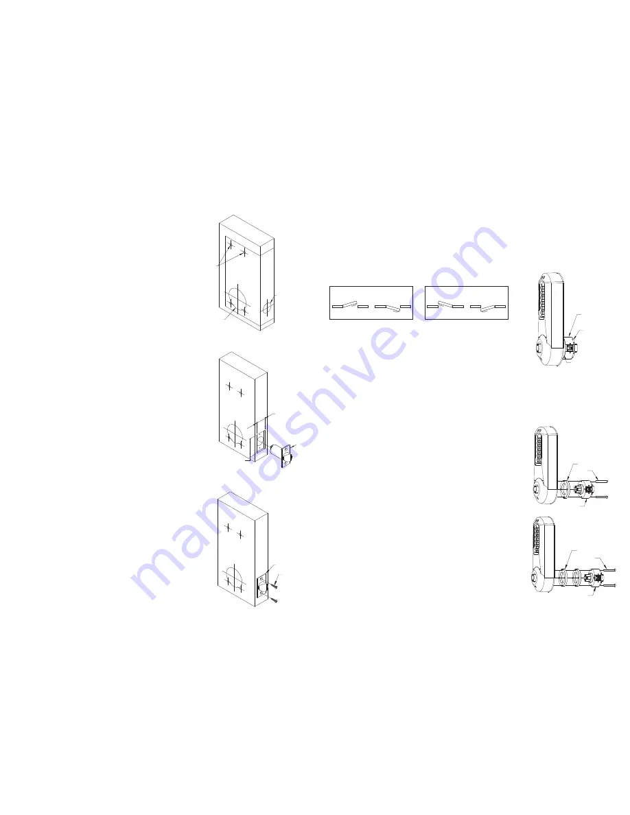
B. LOCK HANDING
The E-Plex 5000 is a non-handed lock that is preassembled for left-hand
door installations.
B-1
Determine the hand of your door. For left hand doors, proceed to Section C.
For right hand doors, follow steps in B-2.
B-2
Remove the two connecting screws (a) from the
cylindrical drive unit (b). Rotate cylindrical drive
unit 180 degrees. Reposition spacer (c) as found
before disassembly. Remount drive unit with the
two connecting screws.
C. DOOR THICKNESS
The E-Plex 5000 lock is preassembled to accommodate standard door
thickness 1
5
⁄
8
" (41 mm) to 2" (51 mm).
C-1 (Reference Figure A) For thinner door
applications of 1
3
⁄
8
" (35 mm) to 1
1
⁄
2
" (38 mm)
remove and discard the two connecting screws (a)
from the cylindrical drive unit (b). Remove and discard
the spacer (c). Remount the cylindrical drive unit using
the two shorter 1
3
⁄
8
" (35 mm) connecting screws also
supplied.
C-2 (Reference Figure B) For thicker door
applications of 2
1
⁄
8
" (54 mm) to 2
1
⁄
2
" (57 mm)
remove the two connecting screws (a) from the
cylinder drive unit (b). Add the extra spacer (c)
supplied. Remount the cylindrical drive unit using
the same two connecting screws (a) just removed.
c
b
a
c
b
a
b
c
a
Left Hand
Left Hand Reverse Bevel
R
LEFT HAND DOOR
Right Hand
Right Hand Reverse Bevel
RIGHT HAND DOOR
L
Figure B
Figure A
A. DOOR PREPARATION
A-1
Place paper template (supplied) onto door and
mark for holes. Drill the four
1
⁄
4
" (7 mm) holes first.
Next drill the 2
1
⁄
8
" (54 mm) cross bore hole. Drill
the 1" (25 mm) hole last.
A-2
Mortise door edge for latch unit faceplate (c)
1
⁄
8
" (3 mm) deep to dimensions shown. Insert
latch unit (a) into the 1" (25 mm) hole, making
certain that the latch bolt bevel faces direction
of closing door.
A-3
Secure the latch to the door using two
3
⁄
4
"
(19 mm) combination screws (b) supplied.
Latch unit faceplate must be flush with
door (c).
1
"
2
1
⁄
8
"
1
1
⁄
8
"
2
1
⁄
4
"
a
c
b
4x
1
⁄
4
"


