7
D. DOOR THICKNESS
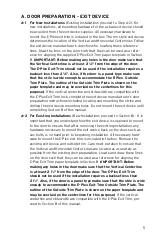
The E-Plex Exit Trim Drive Unit (a) has a spring
loaded tailpiece (b) and is preassembled to accom-
modate standard door thickness from 1
3
⁄
4
" to
approximately 2
1
⁄
8
" for most applications. For
Doors up to 2
1
⁄
4
" inches it may be necessary to
add a spacer to increase the projection of the tail-
piece. If this is required, first remove and discard
the two connecting screws (c) from the Drive Unit
(a). Add spacer (d), and remount using the two longer 1
5
⁄
8
" (41 mm)
connecting screws supplied in the thick door accessory package.
E. ASSEMBLE OUTSIDE UNIT TO
UNIVERSAL MOUNTING PLATE
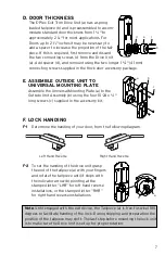
Assemble the Universal Mounting Plate (a) to the
Outside Unit Assembly (b) using the four 10-24 x
3
⁄
4
"
long screws (c) supplied in the accessory kit.
F. LOCK HANDING
F-1
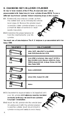
Determine the handing of your door, from the following diagram.
F-2
To set the handing of the drive unit grasp
the end of the tailpiece (a) with your fingers
and rotate the tail piece until it stops with
the indicator arrow (b) pointing at the
stamped letter “LHR” for left hand reverse
installations, or the stamped letter “RHR”
for right hand reverse installations.
Note:
Until engaged with the exit device, the Tailpiece (a) is free to swivel 180
degrees to facilitate handing of the lock. During shipping and preparation the
position of the tailpiece may shift. The last step before mounting the lock unit
is to make sure the Drive Unit is set up for proper rotation.
Left Hand Reverse
Right Hand Reverse
R
H
R
L
H
R
d
b
a
c
c
a
b
b
a
Summary of Contents for E-Plex 5X10
Page 1: ...5X10 EXIT TRIM MODELS INSTALLATION INSTRUCTIONS...
Page 11: ...Notes...
Page 19: ...15 Notes...


