13
12
I-10
Insert the lever release tool (d) into the small hole (f) under lever as
shown. Gently push lever catch up until it clicks. Remove tool, then
remove outside lever (a).
Note
: You may want to use needle nose pliers for some tailpieces.
Insert the release tool (d) into the small hole (f) under the lever as shown.
Gently push lever catch up until it clicks. Remove tool, then remove the outside
lever (a).
Note:
Do not shut door until installing batteries and testing operation as
outlined in the following two sections.
J. INSTALLING THE BATTERY PACK AND
COVER/CHANGING BATTERIES
J-1
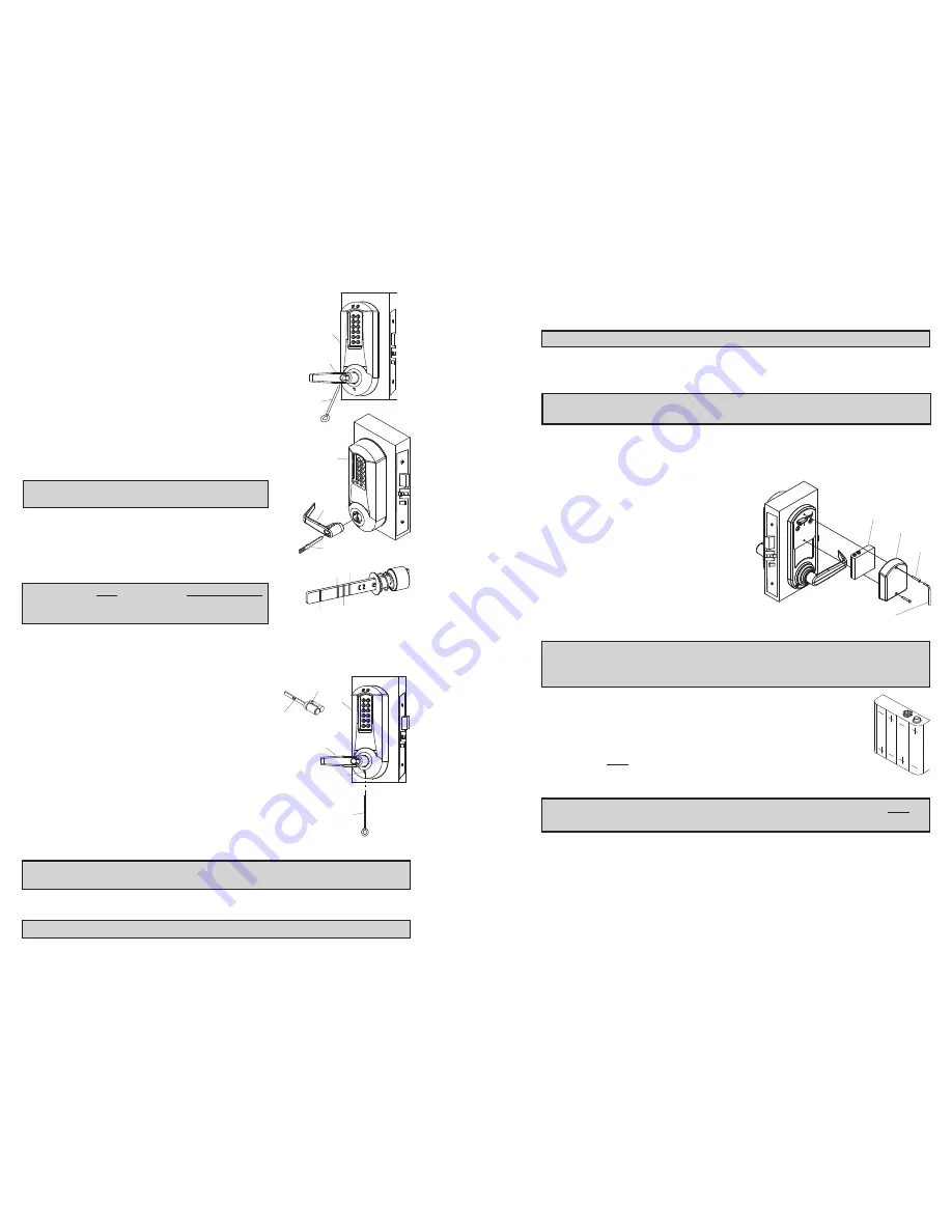
To install the battery pack (f) and
cover (g), snap the cable connector
onto the top of the loaded battery
pack. Then place the battery pack
into the cover, terminals at the top.
Put the two security screws (h) into
the cover and fasten the cover to
the inside housing with the security
screw tool (i).
Caution
: Over-tightening these screws could strip
the threads in the housing or crack the cover.
Warning
: If the lock goes without power for more than two minutes, you will
lose the lock’s current date and time only. If this happens, program the lock
with the correct date and time. Refer to Operations Manual.
J-2
Remove the two screws (h) securing the battery cover to the
housing, using the security screw tool (i) provided with your
lock.
J-3
Remove the four depleted batteries and install four new
Alkaline
only
AA batteries. Ensure that each battery is
installed in the proper direction as shown at each battery
location in the battery holder (f).
Warning
: Do not install a 9V battery. Your lock operates on 4 alkaline
only
AA
batteries (6V). A 9V will ruin the electronics in the lock, and void your warranty!
J-4
Reconnect the battery cable. Place the battery holder into the cover.
Screw the back cover onto the inside housing, ensuring that the cable is
not trapped under the edge of the cover.
Caution
: Over-tightening these screws could strip the threads in the housing or
crack the cover.
I-2
Insert the outside lever (a) until it is flush to the
outside unit assembly (b). To secure the outside
lever, insert the release tool (d) (or screwdriver) into
the outside lever as shown, and slide the lever
catch down until it clicks. Make certain lever is
attached before installing the core.
I-3
Insert the supplied tailpiece (e) vertically into the
outside lever as shown. Make certain that you
rotate the tailpiece so that it will align with the
interchangeable core. For screw cap type cylinders
(Schlage) (g), the tailpiece must be assembled to
the cylinder first as shown (vertical position).
Insert the interchangeable core into the outside
lever.
Note
: To remove the outside lever from the
outside unit assembly, follow steps below.
I-4
Remove the interchangeable core (g).
Then remove the tailpiece (e).
I-5
For ASSA/Medeco/Yale interchangeable/remov-
able cylinders, the tailpiece must be prepped for
the desired length before installation.
When using a Yale cylinder on a cylindrical latch
application, measure the door thickness of the
intended application.
I-6
Notice the score marks on the flat portion of the ASSA/Medeco/Yale tail-
piece. Using the diagram to the right, locate the score mark on your tail-
piece that matches your cylinder prep for the intended application, and
break the tailpiece off accordingly.
I-7
Using 2 pairs of pliers, break the tailpiece to
the desired length of the intended applica-
tion by holding 1 pair of pliers on the good
side of the score mark and one pair on the
other side of the score mark. Slowly move
the 2nd pair of pliers up and down until the
unneeded portion of the tailpiece breaks free.
I-8
Insert the Medeco tailpiece (e) vertically into the out-
side lever as shown. Make certain that you rotate the
tailpiece slightly so that it will align with the inter-
changeable/removable cylinder. Insert the inter-
changeable/removable cylinder into the outside
lever.
Note
: To remove the outside lever from the outside unit assembly, follow
steps below.
I-9
Remove the interchangeable/removable cylinder. Then remove the tail-
piece (e).
Note
: You may want to use needle nose pliers for some tailpieces.
e
a
b
d
b
a
vertical
g
b
d
f
a
f
h
i
g
a
c
d
b


