PK3520_09_07 • REMOTE ACCESS CONTROLLER - 660G XT
10
Step 6: Connect wiring
CAUTION: Do not exceed the maximum cable length
indicated by the manufacturer of products being
connected.
!
CAUTION: Refer to the wiring diagram in Annex A, or
refer to label located inside the enclosure's cover.
Follow the applicable steps depending on what
peripherals need to be installed.
!
IMPORTANT: Every wire for the peripherals and power
adaptor must pass through a strain relief as connected
per Step 4.
!
IMPORTANT: For peripherals, choose the appropriate
wire gauge depending on the distance between the
peripheral being installed and the controller board (B)
Refer to manufactures wire gauge installation selections.
Respect all building codes and local legislation relative
to the wiring required.
!
1.
If the controller box is to be interfaced to a fire alarm
panel, remove the jumper wire connected between pins
3 and 4 of J18 on the controller board (C) and complete
the fire panel installation as desired.
2.
If a request to exit (REX) button (S) is being used, mount
the button at the desired location and run a 2-conductor,
cable from the control panel to the REX button location.
Connect as per Annex A, Table 1.
NOTE:
Refer to manufacturer’s wire gauge installation
selections.
NOTE:
A motion detector may also be used for request to exit.
If this is required, use the same connection instructions
as indicated above.
3. If a remote unlock button (U) is being used, mount the
button at the desired location and run a 2-conductor
cable from the controller board (C) to the remote unlock
button location. Connect as per Annex A, Table 1.
NOTE:
Refer to manufacturer’s wire gauge installation
selections.
4. Install a 2-conductor cable from the control panel to the
location of the electric strike (Q) or electromagnetic lock
(R). Connect as per Annex A, Table 1.
NOTE:
Refer to manufacturer’s wire gauge installation
selections.
5. Install the diode across the terminals of the electromagnetic
lock (R) or, using the crimp connectors (AC) provided in
the hardware bag, install the diode across the two wires
of the electric strike (Q). Do not reverse the diode polarity,
as indicated on the wiring diagram in Annex A.
CAUTION: Diode must not be in contact with
electromagnetic lock (R) or electric strike (S), or a
short could be created. Diode ends might need to be
cut shorter.
!
NOTE:
This step is not necessary if installing a Rutherford
Controls 83xx series electromagnetic lock.
6. Following local building code requirements, mount the
electric strike (Q) or electromagnetic lock (R) or Garage
Door Opener (V) in the desired location and connect as
per manufacturers’ instructions. For connections into the
Controller box, connect as per Annex A Table 1.
7. If the Tamper switch needs to be connected to the
premise alarm system, disconnect the wires from J7-1
and J7-2 and run a 2-connector cable from the tamper
switch to the premise alarm system.
IMPORTANT: The tamper switch’s polarity is such that
when the door is closed the switch itself is also in a
closed state. Ensure that the wiring to the premise alarm
system is done accordingly to prevent false alarms.
!
Step 7: Mounting and wiring keypads
NOTE:
All keypads must be installed on a flat surface.
Up to two keypads can be installed with the 660G XT; one
ingress and one egress.
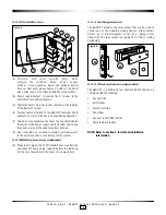
Figure 10
3 x 4 Wall mount
or
2 x 6 Narrow
4.0 System Installation Overview
(Continued)

