background image

EN

Page 9 

Errors and modifications excepted. 

09.02.2009

Mounting Instructions Mechanical Combination Locks
LA GARD 947/ 985/ 3330/ 3332/ 3370/ 3390 


the bolt or the relocker might be damaged.
With the lock 1947 the lever has to be dropped and the bolt has to be slid-in before the cover 
can be assembled.

Lock 3370: 
Removing the cover is not necessary for mounting the 3 screws. Just fit the screws from 
behind the lock through the cover and the housing.

Lock 3390:
Removing the cover is not necessary for mounting the 3 screws. Just fit the screws from 
behind the lock through the cover and the housing. The short screw fits in the hole with the 
circular mark. Note: The bolt must remain in the retracted position during the entire installation 
process. If the bolt becomes extended during the installation process, open the lock according  
point 8. and continue the installation. After mounting and testing lock and dial, install the cover 
insert. Press the insert into the cover using even pressure. The insert is designed to prevent 
spline key movement.

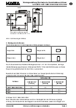
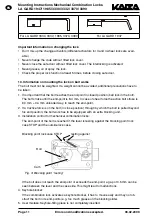
The bolt work must block the extended bolt (8 mm) sufficiently on both sides (in opposite 
directions). If only one side is blocked and the bolt pressure exceeds 1 kN, a bolt support must 
be fixed on the opposite side. The tolerance between closing point respectively support and 
bolt is 0.5 - 1 mm, the bolt counter pressure is 1 KN max.

If parts of the bolt work are attached to the bolt (option code RLG004 or RLG005), see point 
10.

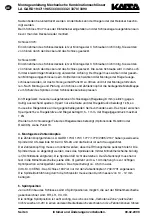
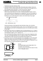
4. Dial assembly

The LA GARD dial & ring combinations 1730/ 1731/ 1777/ 1779/ 2085/ 2107 have a spindle 
with US-thread 5/16-40 UNS-2A and the dial is splined on 43.
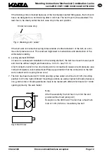
Assemble the ring so that the Opening Index is vertical. Cut the spindle so that the spindle-end 
levels with the cam. The spindle must not stick out. Carefully thread (clockwise) the spindle 
into the drive cam until tight. Next, rotate (counter-clockwise) approx. 1 turn until the groove in 
the spindle is aligned with the correct spline position. Tolerance approx. 0.5 mm axial. 
VdS Class 3/CEN C: 1947 is only approved with the dial 1730/1731. The spindle lead through 
of the safe door must have a diameter of 10-12 mm.

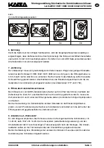
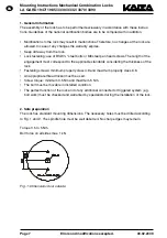
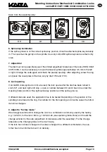
5. Spline key position

Depending on the installation of the lock, 4 spline key positions are possible. They are indi-
cated on the cam: RH, LH, VU, VD.
The correct spline key position is very important, because otherwise the „prohibited area“ 
(last number not between 0-20) moves in another operational range and might lead to lock 
malfunctions.

Summary of Contents for LA GARD 1947

Page 1: ...t werden Die notwendige Einschraubtiefe muss den gültigen Normen unter Berücksichtigung der Schlossdicke entsprechen Befestigungsschrauben mindestens Festigkeitsklasse 4 8 maximal Festigkeitsklasse 8 8 Es muss eine geeignete Schraubensicherung verwendet werden Anzugsdrehmoment der Schrauben mindestens 3 5 Nm maximal 5 Nm Der Riegel muss in der eingebauten Position frei bewegt werden können Die ein...

Page 2: ...auben US Gewinde BSW 20G oder M6 Schrauben von Kaba Mauer Anzugsdrehmoment 3 5 bis 5 Nm zu verwenden Bestellnummern M6 Schrauben von Kaba Mauer es müssen jeweils alle dem Schlosstyp entsprechenden Schrauben M6 einer Zeile bestellt werden Schloss Schrauben M6 1 260 601 007 10 mm 1 260 602 502 25 mm 1 260 603 001 30 mm 1947 1985 3330 3332 2 x 2 x 3370 3 x 3390 1 x 2 x Schlösser 1947 1985 3330 3332 N...

Page 3: ...nur eine Seite und der Riegeldruck übersteigt 1 kN so muss eine Riegelstütze an der gegenüberliegenden Seite vorhanden sein Das Spiel zwischen Sperrpunkt bzw Riegelstütze und Riegel beträgt 0 5 1 mm der Riegelgegendruck maximal 1 kN Werden am Schlossriegel Teile des Riegelwerkes befestigt Optionscode RLG004 oder RLG005 siehe Punkt 10 4 Montage des Zahlenknopfes Die Zahlenknopfgarnituren LA GARD 17...

Page 4: ... in den Zahlenknopf eingesetzt werden bei Zahlenknopf 1777 und 1730 8 Öffnen des Kombinationsschlosses Beim Einsatz von LA GARD Zahlenknöpfen Keilnut auf 43 öffnet das Schloss nachdem der Zahlenknopf 5 x links 50 anschließend nach rechts bis Stop gedreht wurde Es muss eine Zahl zwischen 90 und 0 unter der Öffnungsmarke stehen Kontrolle der richtigen Splintposition und Keilnut Bei der Verwendung vo...

Page 5: ...t dass der Schlossriegel in vorgeschlossener Position den Rastpunkt Kugelarre tierung am Schlossriegel erreicht Der Riegelweg bis zum Rastpunkt beträgt 8 4 mm Bei Schubkräften beträgt der aktive Riegelweg 8 0 mm 0 4 mm unbelasteten Weg um den Rastpunkt zu erreichen 2 Sollte beim Riegelwerk in der vorgeschlossenen Position ein Zug auf den Schlossriegel auftreten der den Schlossriegel über den Rastp...

Page 6: ... des Schlossriegels möglich machen tritt ein enormer Riegeldruck auf Durch diese Überlastung kommt es zu Schlossfehlfunktionen bis hin zur Zerstörung der Kombina tionsscheiben 6 Sperrelement RISTOW Der nachträgliche Einbau des Sperrelementes muss so vorgenom men justiert werden dass der Schlossriegel seinen Rastpunkt mit Sicherheit erreicht und dort unbelastet ist Spiel 0 4 mm siehe 10 1 3 Eine zu...

Page 7: ...screws The length of the engagement must correspond to the applicable standards considering the thickness of the lock Fastening screws minimum property class 4 8 and maximum property class 8 8 An appropriate thread locker must be used Screw torque minimum 3 5 Nm and maximum 5 Nm The bolt must be movable in installed condition The perfect function of the lock and of any additional connected or trig...

Page 8: ... BSW or M6 screws torque 3 5 to 5 Nm which can be ordered at Kaba Mauer Order numbers M6 screws from Kaba Mauer all corresponding M6 screws from one line have to be ordered Lock M6 Screws 1 260 601 007 10 mm 1 260 602 502 25 mm 1 260 603 001 30 mm 1947 1985 3330 3332 2 x 2 x 3370 3 x 3390 1 x 2 x Locks 1947 1985 3330 3332 After removing the lock cover the 4 assembly holes are accessible Note To ex...

Page 9: ...rections If only one side is blocked and the bolt pressure exceeds 1 kN a bolt support must be fixed on the opposite side The tolerance between closing point respectively support and bolt is 0 5 1 mm the bolt counter pressure is 1 KN max If parts of the bolt work are attached to the bolt option code RLG004 or RLG005 see point 10 4 Dial assembly The LA GARD dial ring combinations 1730 1731 1777 177...

Page 10: ...nd 1731 8 Lock opening If LA GARD dials splined on 43 are used the lock opens after the dial has been turned 5 x left 50 and next right until stop open A number between 90 and 0 has to be under the Opening Index control of the right spline key position and the spline groove If different dials are used the application has to be tested Depending on the position of the spindle groove towards the ring...

Page 11: ...in the bolt The bolt stroke until the end point is 8 4 mm In case of shear force the active bolt stroke is 8 0 mm 0 4 mm unloaded way to reach the end point 2 If a tractive force is on the bolt in close position through by which the bolt is pulled beyond his end position the bolt work has to be equipped with an extra blocking unit 3 Installation control for mechanical combination locks The end poi...

Page 12: ...case of a subsequent installation of the locking element the bolt must reach its end point and must be without weight end tolerance 0 4 mm see 10 1 3 A bolt connection which is too short end point is not reached causes an end pressure see 10 5 which leads to lock malfunctions Please pay attention that the connection to the bolt work is direct and no spring forces occur 7 The lock has been tested w...

Reviews: