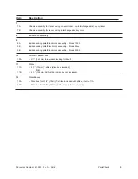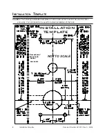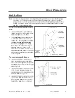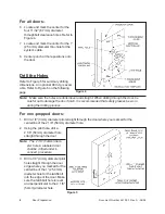
Document Number 481.093 Rev. A - 06/04
10
I
NSTALLATION
Install the Latchbolt
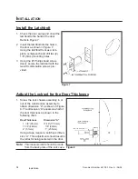
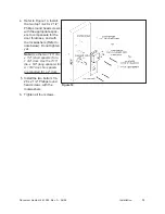
1. Check the door swing and orient the
latchbolt to the hand of the door.
Refer to Figure 7.
2. Insert the latchbolt into the hole in
the door as shown in Figure 7.
Using the latchbolt front as a tem-
plate, centerpunch and drill two (2)
1/8” (3mm) mounting holes.
3. Using the #1 Phillips head screw-
driver, secure the latchbolt with the
two #8 combination screws pro-
vided.
Adjust the Lockset for the Door Thickness
1. Screw the lock chassis assembly in or
out of the outside case assembly to
obtain dimension “A” as shown in Figure
8. The dimension “A” equals one-half of
the door thickness as shown in the
following chart.
Door Thickness
Dimension “A”
1 3/8” (35mm)
11/16” (17.5mm)
1 3/4” (44mm)
7/8” (22mm)
2” (51mm)
1” (25.5mm)
Using a tape measure, set/check dimen-
sion “A”. This adjustment should result in
the retractor being centered in the door.
Note:
This measurement should be made
from the back plate of the lock case.
Figure 7
Figure 8
Installation
Summary of Contents for PowerLever 1550
Page 1: ...PowerLever Door Lock Series INSTALLATION GUIDE Models 1550 4550 4560 PROX 9000 ...
Page 4: ...SPECIFICATIONS 22 Electronic Specifications 22 Hardware Specifications 22 TROUBLESHOOTING 22 ...
Page 28: ...Document Number 481 093 Rev A 06 04 24 ...
Page 29: ...NOTES ...
Page 30: ......
Page 31: ......


