17
Add Keypad Access User(s)
Note: You do not need to perform this operation if you are downloading users from the PC.
Note: If at any time during the procedure the lock power drops below a sufficient level for operation, the lock will
continually beep and flash the red LED, prompting the user to depress the outside lever to provide additional power
within 5 seconds.
Step
Detailed Instructions
1.
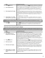
Power lock.
Power the lock by depressing the outside lever.
2.
Enter Master User or a
Enter the Master User or a Manager User combination on the lock keypad.
Manager User combination.
The lock will beep/flash the green LED on each keystroke entered. If the
Clear key is pressed during data entry, the lock responds with one beep/
flash of the green LED fol lowed by the red LED, and all digits of the com bi -
na tion must be re-entered.
The lock re sponds with three beeps/flashes of the green LED to indicate
available entry. If the combination is not valid, the lock responds with three
beeps/flashes of the red LED.
3.
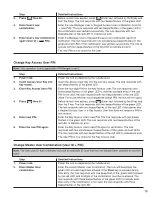
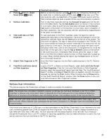
Press then 2.
Before re-lock time expires, press (Enter key) followed by the 2 key.
The lock re sponds with two beeps/flashes of the green LED.
4.
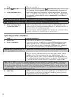
Enter Keypad Access User ID.
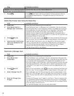
Enter a User ID for a Keypad Access User. The lock responds with two
beeps/flashes of the green LED if the User ID is valid.
Note: The User ID selected must be in the range from 0 to the number of keypad users minus one.
5.
Enter Access User ID again.
Enter the Keypad Access User ID again for verification. The lock responds
with two beeps/flashes of the green LED. The lock responds with two beeps/
flashes of the red LED if the User ID was un con firmed, or if the User ID was
already in use, or no space was found in the Keypad Access User Table.
6.
Enter one-digit user access
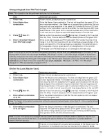
Enter a one-digit value to select the access schedule for the User ID. The
schedule.
value must be in the range of 0–6 where 0 in di cates no access time restric-
tion. The lock responds with four beeps/flashes of the green LED if the
access schedule des ig na tion is valid. The lock responds with two
beeps/flashes of the red LED to indicate an error. Refer to the “Access
Schedules” section on page 8 for more detailed information.
Note: If the value of “0” is assigned for the access schedule, the Keypad Access User can access the lock at all
times. To assign a value other than “0”, defined access schedules must have been down loaded from the PC.
The Keypad Access User is now added to the lock with the entered User ID
and a default PIN of all 0’s if PIN length is not 0.
7.
Repeat Steps 4–6 to add
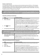
If additional Keypad Access Users are to be added, repeat Steps 4-6 until all
more users or go to Step 8.
User IDs have been added. If no ad di tion al Keypad Access Users are to be
added, go to Step 8.
Caution: If you are adding multiple Keypad Access Users, you may need to depress the outside lever to provide
additional power.
8.
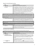
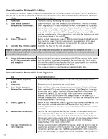
Press .
Press (Enter key) to exit this procedure. The lock responds with two
si mul ta neous beeps/flashes of the green and red LEDs and exits this
procedure.
Note: If PIN length is not 0, a default PIN of all 0’s is assigned to the new Access User. The Access User must
change this default PIN before the Access User’s combination can be used to open the lock. Refer to the “Change
PIN” section for instructions on chang ing an Access User’s PIN.
Note: To change an access schedule assignment for a user at the lock, the user must first be deleted and then re-
added to the lock with the new schedule assignment. The other method to change an access schedule occurs at the
PC and requires downloading of the users into the lock again after the change has been made at the PC.
Summary of Contents for PowerLever 455 Series
Page 1: ...PowerLever 455x Operating Instructions...
Page 37: ...37 Notes...
Page 38: ...38 Notes...
Page 39: ...39 Notes...

