background image

7

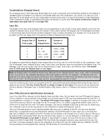
Combinations (Keypad Users)

For all keypad users, the PowerLever Model 455x Door Lock is accessed via a com bi na tion entered at the keypad. A
Variable Length Combination is a feature of the Model 455x lock. The com bi na tion can consist of as little as a one-
digit User ID or the length can be up to eight digits in length and consist of a User ID followed by a PIN. Re gard less
of the combination length, a com bi na tion will always be unique to a given user. 

The default com bi na tion length is

eight digits (four-digit User ID + four-digit PIN). 

User IDs 

The length of the User ID for Keypad Users will vary depending on the number of Key Users defined in the lock. The
number of Keypad Users (3,000 minus the number of Key Users) defines the Keypad User ID field length ac cord ing
to the following table. Note that the number of Keypad Users is always calculated as a multiple of 5. In all cases the
possible User IDs will range from 0 through the number of Keypad Users minus one. 

Keypad User ID

Number of

Number of

Field Length

Keypad Users

Key Users

1

5 – 10

2,990 – 2,995

2

15 – 100

2,900 – 2,985

3

105 –  1,000

2,000 – 2,895

4

1,005 – 3,000

0   – 1,995

All op er a tions per formed by Keypad Users require the entry of the User ID as the first digits of the com bi na tion. User
IDs for Manager Users, Keypad Access Users, Audit Users, and Service Users are assigned by the Master User. The
Man ag er User can also assign User IDs for Keypad Access Users, Audit Users, and Service Users. The default
User ID field length for Keypad Users is four digits.

Note: All Keypad Users including the Master User, Manager Users, Keypad Access Users, Audit  Users and Service
Users occupy one of the available keypad User IDs when added to the lock. For example, if the Master User acti-
vates the lock and changes the default com bi na tion from “00000000” to “00011234” the Master User then occupies
the User ID “0001”. No other Keypad User can then be assigned the User ID of “0001”. 

User IDs for Key Access Users are assigned at the PC using the PowerLever Software when a Key Access User is
added to the system. The Key Access User ID is always a length of four digits. The User ID can be used at the
lock by a Master or Man ag er User to Enable/Disable a Key Access User or to Delete a Key Access User from the
lock.

User PINs (Personal Identification Numbers)

Use of the User PIN is optional for both Keypad Users and Key Users. At lock setup, the User PIN length for Keypad
Users is defined. It can be defined to be a length of 0 (in which case no PIN has to be entered with the User ID) or it
can be defined to a length of 1-4 digits. The default PIN length is four digits. If defined to a length other than 0, the
User PIN can be any value in the range from all 0’s through all 9’s. It is initially as signed the default value of all 0’s
(which will not open the lock until it has been changed), and can be changed at any time by the user for added secu-
rity. If defined, it serves as the second part of the com bi na tion, always following the User ID.

The User PIN field length for each individual Model 455x Key User is defined at the PC. The Per son al Iden ti fi er
Smart Key is pro grammed using the PowerLever software, and the PIN length for each Key User is set when the 
Key User is added to the system at the PC. The PIN can be defined to be a length of 0 (in which case no PIN has to
be entered after inserting the Smart Key into the Smart Key reader) or it can be defined to a fixed length of 4 digits.
The default PIN length is four digits. If defined to fixed length of 4 digits, the User PIN can be any value in the
range from 0000 through 9999. The default PIN may initially be assigned a random value (which will not open the
lock until it has been changed), and can be changed at any time by the user for added security. If defined, the PIN
must be entered via the keypad after inserting  the Smart Key into the lock key reader.

Summary of Contents for PowerLever 455 Series

Page 1: ...PowerLever 455x Operating Instructions...

Page 2: ...ck Personnel Classifications 6 Lock Personnel Classification Activity Chart 6 Combinations Keypad Users 7 User IDs 7 User PINs 7 Access Schedules 8 Communicating with the Lock 8 Operating Conventions...

Page 3: ...ng the Smart Key 28 Deactivate a Manager User 28 Change Keypad User PIN Field Length 29 Shelve the Lock Master User 29 Retrieve Audit Records 30 Audit Record Retrieval Via SA Key 30 Audit Record Retri...

Page 4: ...e simultaneous flash of the green and red LEDs accompanied by a low volume beep indicates that the lock is powered Each additional depression of the lever will result in this same response Extended op...

Page 5: ...User classifications of personnel can perform various operations at the lock Master User The Master User is the top level manager who performs the initial lock setup activities and can pro gram all l...

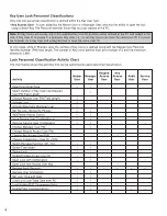
Page 6: ...tiple of 5 and the maximum allowed is 2 995 Lock Personnel Classification Activity Chart The chart below shows the activities that can be performed by each personnel classification Keypad Key Master M...

Page 7: ...n occupies the User ID 0001 No other Keypad User can then be assigned the User ID of 0001 User IDs for Key Access Users are assigned at the PC using the PowerLever Software when a Key Access User is a...

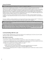
Page 8: ...define Access Time Windows for a specific Key User when adding the Key User to the PC System page 17 Note To change an access schedule assignment for a user at the lock the user must first be deleted...

Page 9: ...outside lever through a 67 degree open and 67 degree restore rota tion After each accepted step of an operation two flashes of the green LED display and two beeps sound prompting you to enter addition...

Page 10: ...he lock shutting down for the programmed penalty time This cycle will continue until a correct combination is entered for a Keypad User or a valid Smart Key is presented for a Key Access User Audit Fe...

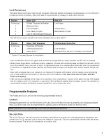
Page 11: ...ved mode the lock will be set up for entry only by the Master User via a combination of all 0 s Within the Shelved Mode the Master User can Define the number of Smart Key Users and Keypad User PIN fie...

Page 12: ...the re lock interval the lock will respond with two simultaneous beep flashes of the red and green LEDs Note If a lock has been Activated and then Shelved the lock returns to a state where it can be...

Page 13: ...he Lock page 29 Master User Manager Users 1 Add Keypad Access User s page 17 2 Delete Keypad User s Using the Keypad page 26 3 Delete Key Access User s Using the Keypad page 27 4 Delete a Key Access U...

Page 14: ...ser PIN Field Length range of 0 4 For a lock that has not been previously configured the lock re sponds with two beep flashes of the green LED if the data entered is accept able For a lock that has be...

Page 15: ...he outside lever 2 Enter Master User Enter the Master User combination The lock will beep flash the green LED combination on each keystroke entered If the Clear key is pressed during data entry the lo...

Page 16: ...uld be entered as 083097 The lock responds with two simultaneous beeps flashes of the green and red LEDs The entered lock time and date are now in effect Set the Re Lock and Wrong Try Limit and Penalt...

Page 17: ...able 6 Enter one digit user access Enter a one digit value to select the access schedule for the User ID The schedule value must be in the range of 0 6 where 0 indicates no access time restric tion Th...

Page 18: ...combination again for verification The lock responds again with two simultaneous beeps flashes of the green and red LEDs if the com bination was verified successfully The lock responds with two beeps...

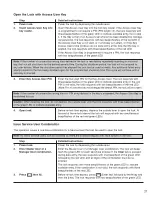
Page 19: ...d LED Note For a User who has not changed the default PIN the lock will not open 4 Press then 51 Before re lock time expires press Enter key followed by the 5 key and then the 1 key The lock responds...

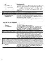
Page 20: ...roke entered If the Clear key is pressed during data entry the lock responds with one beep flash of the green LED followed by the red LED and all digits of the combination must be re entered Caution W...

Page 21: ...indicate available entry If the lock PIN is not valid the lock responds with two beeps flashes of the red LED Note For a User who has not changed the default PIN the lock will not open Note If the num...

Page 22: ...if the access schedule designation is invalid Refer to the Access Schedules section on page 8 for more detailed information Note If the value of 0 is assigned for the access schedule the user can acc...

Page 23: ...pressed during data entry the lock responds with one beep flash of the green LED followed by the red LED and all digits of the combination must be re entered The lock responds with three beeps flashe...

Page 24: ...User combination flash the green LED on each keystroke entered If the Clear key is pressed during data entry the lock responds with one beep flash of the green LED followed by the red LED and all digi...

Page 25: ...to disable If additional Keypad Users are to be disabled repeat steps 4 5 until all User more Keypad Users or go to until all User IDs are disabled If no additional Keypad Users are to be dis step 7 a...

Page 26: ...er Key User ID again Enter the four digit Key User ID again for verification The lock responds with four beeps flashes of the green LED The lock responds with two beeps flashes of the red LED if the U...

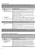
Page 27: ...ll continually beep and flash the red LED prompting the user to depress the outside lever to provide additional power Step Detailed Instructions 1 Power lock Power the lock by depressing the outside l...

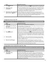
Page 28: ...eader red LEDs and exits this procedure The lock responds with two beeps flashes of the red LED if the Access User s Key is not valid The Key Access User is now deleted Deactivate a Manager User Step...

Page 29: ...ly be zero filled to the left to match the new length Example PIN length 3 PIN 111 PIN length changed to 4 PIN automatically changed to 0111 Shelve the Lock Master User Step Detailed Instructions 1 Po...

Page 30: ...re lock time expires press Enter key followed by the 0 key and then the 0 key again The lock responds with one beep flash of the green LED every second until the SA key is inserted into the lock key r...

Page 31: ...om of the audit record list 7 Attach Palm Organizer to PC Insert the Palm Organizer into the Palm cradle attached to the PC Perform Hot Sync 8 View Print audit data stored Logon to the PC software and...

Page 32: ...ock responds with two simultane ous beeps flashes of the green and red LEDs The lock user table has now been downloaded to the SA Key User Information Retrieval Via Palm Organizer Step Detailed Instru...

Page 33: ...Load Lock User Table Holiday Daylight Savings Time Data Created on PC This feature provides the function to load Lock User Table Holiday Daylights Savings TIme data created with the PowerLever Door L...

Page 34: ...en finished click the Close button on the List of Locks Processed window After all locks have been processed perform a Hot Sync operation with the Palm 3 Connect Palm Organizer to Connect the Palm Int...

Page 35: ...multaneous beeps flashes of the green and red LEDs Enable Palm Communications This feature provides the function to set up communications between the lock and the Palm organizer To enable Palm communi...

Page 36: ...ypad User s from Lock Using the Keypad p 26 and then 31 Delete Key Access User s from Lock Using the Keypad p 27 and then 32 Delete Key Access User from Lock Using the Smart Key p 28 and then 40 Load...

Page 37: ...37 Notes...

Page 38: ...38 Notes...

Page 39: ...39 Notes...

Page 40: ...Kaba Access Control 2941 Indiana Avenue Winston Salem NC 27105 USA Tel 800 849 8324 336 725 1331 Fax 800 346 9649 336 725 3269 www kabaaccess com 438 030 0210...

Reviews: