background image

© SAFLOK, all rights reserved.

INS_QTMIIMTRFID_2_12

QuantumII

TM 

MT RFID Installation Instructions

Pg 5 of 8

Installing the lock trim 

(continued)

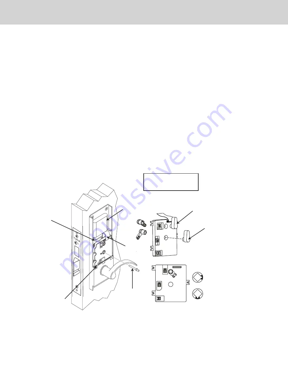
9.  Connect ribbon cable, motor cable, and power wire to the PCB. See Fig. 6. Be sure not to crease ribbon.

10.  Watch for the green LED on the card reader to flash four times while you connect the battery wire to the PCB.  

The green light indicates that the PCB has reset.


Important:

 The battery wire should be the last connection made to the PCB.

11.  With the dead bolt retracted, insert the long end of the dead bolt spindle assembly through the PCB switch  

cam hole and into the mortise dead bolt hub. The indicator marks on the switch cam should be at the right  
(3:00 position) when the mortise dead bolt is retracted (see Fig. 6). The retaining ring should rest on the switch  
cam when fully inserted (the proper positioning of the cam will allow the door to be opened when the dead bolt  
is retracted and block entry when the dead bolt is thrown for privacy, except when emergency keycards are used). 
Position dead bolt spindle assembly into cam assembly.


Important:

 As illustrated in Fig. 3, be sure that the cam is in correct orientation. 

12.  Install the inside escutcheon with the thumb turn pointed upward.  


Fig. 6

Battery Wire

Motor Wire

Battery

Ribbon

Cable

Dead Bolt

Spindle

Position for the ADB mortise

lock assembly

Position for the STD mortise

lock assembly

Route the ribbon over the 

battery. Do not crease 

ribbon connector.

3:00 Position
ADB Mortise

OR

6:00 Position
Standard Mortise

Summary of Contents for Saflok QuantumII MT RFID

Page 1: ... property is confidential and intended for the sole use of the addressee s so named Any misuse of this confidential information contained herein may result in legal action by Computerized Security Systems dba SAFLOK and its parent company Proximity Reader Assembly A21710 COLOR Mortise see Mortise Options table Scalp Plate 51190 COLOR Outside Lever Trim A20970 HAND COLOR Screw Pack A29070 COLOR Str...

Page 2: ...nd confirm that the existing door edge prep is appropriate for the SAFLOK mortise lock Drill fixture If you are using a SAFLOK drill fixture position and clamp the fixture on the door The fixture has two positioning posts that rest inside the mortise establishing the proper backset for the trim When the fixture is clamped its surfaces should be parallel with the door surfaces and door edges Not al...

Page 3: ...pinched or pulled as the mortise is inserted into the pocket 4 Attach the mortise front plate to the door using the two mortise screws 12 x 1 1 4 screws for wood doors 12 24 x 3 8 screws for metal doors Be sure that the screws are fully tightened Important DO NOT leave the screws loose The screws must be fully tightened before the trim is installed If you must leave the mortise loose to install th...

Page 4: ...r Do not pull on the ribbon cable DO NOT CREASE THE RIBBON CONNECTOR 3 Position the inside trim on the inside of the door 4 Secure inside trim to the proximity card reader assembly to the inside trim using three M5 x 31 mm screws Important Do not fully tighten the screws at this point 5 Align the outside lever trim with the diagonal holes located on either side of the mortise hub and secure it usi...

Page 5: ... the switch cam should be at the right 3 00 position when the mortise dead bolt is retracted see Fig 6 The retaining ring should rest on the switch cam when fully inserted the proper positioning of the cam will allow the door to be opened when the dead bolt is retracted and block entry when the dead bolt is thrown for privacy except when emergency keycards are used Position dead bolt spindle assem...

Page 6: ...nd Interrogator LPI probe with the LPI R device cable Test the functioning of the lock as discussed in the following section and in the programming manual before closing the door When the construction key is used the green and red LEDs will blink together indicating that the lock s time and date are not set 15 For humid outdoor environments apply dielectric grease inside the USB connector after pr...

Page 7: ...er to the table below Lock Communication Electronic Function Description Red and green LEDs flash Time and date not set use the Quantum MT RFID LPI probe to reset nine times simultaneously Yellow LED flashes 12 times Dead bolt is thrown or switch cam is not properly aligned Yellow LED flashes two times Keycard not allowed OR keycard cancelled by new keycard Red and green LEDs flash Low battery con...

Page 8: ...2 times when the dead bolt is extended and a guest hotel keycard is used All keycards function to the specifications of the properties key design Door function Door closes and latches with little or no interference Dead bolt extends fully through the strike plate without interference door closed Spacing between door edge and inside door jamb does not exceed 3 16 door closed Note If bumpers or othe...

Reviews: