A.
DOOR PREPARATION
A-1
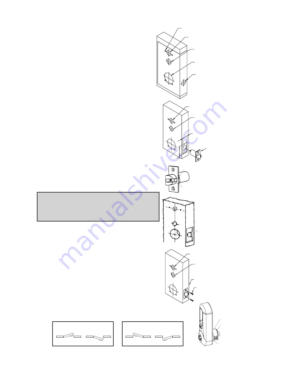
Place paper template (supplied) onto door
and mark for holes. Drill the four
1
⁄
4
" (7
mm) holes first. Next drill the 2
1
⁄
8
" (54
mm) cross bore hole. Drill the 1" (25 mm)
hole last.
A-2
For Models 504x & 505x only. When
installing Model 502x, skip to step A-4
.
Passage feature models require an
additional 1” (25 mm) hole in the door face
(see “a” in the illustration to the right).
A-3
For Models 503x & 505x only. When
installing Models 502x or 504x models,
skip to step A-4
. Inside code change models
require an additional 1” (25 mm) hole in the
door face (see “b” in the illustration).
A-4
Mortise door edge for latch unit faceplate (c)
1
⁄
8
" (3 mm) deep to dimensions shown. Insert
latch unit into the 1" (25 mm) hole, making
certain that the latch bolt bevel faces
direction of closing door.
Note
: If using a
3
⁄
4
" (19 mm) latch, the edge of the
latch bore hole must be prepped to accomodate
the anti-friction hinge. (The location of the anti-
friction hinge depends on the door handing).
A-5
Secure the latch to the door using two
3
⁄
4
"
(19 mm) combination screws (d) supplied.
Latch unit faceplate must be flush with door (e).
B.
LOCK HANDING
The Simplex 5000 is a non-handed lock that is
preassembled for left-hand door installations.
B-1
Determine the hand of your door. For left
hand doors, proceed to Section C.
For right hand doors, follow steps in B-2.
4
4 x
1
⁄
4
"
b 1" (for models
503x & 505x)
a 1" (for models
504x & 505x)
b 1" (for models
503x & 505x)
Mortise approx.
5
⁄
16
" (8 mm)
extra depth to
allow clearance
of anti-friction
hinge
b 1" (for models
503x & 505x)
a 1" (for models
504x & 505x)
a 1" (for models
504x & 505x)
2
1
⁄
8
"
1"
1
1
⁄
8
"
c
Anti-friction hinge
Anti-friction device
e
d
2
1
⁄
4
"
Left Hand
Left Hand Reverse Bevel
R
LEFT HAND DOOR
Right Hand
Right Hand Reverse Bevel
RIGHT HAND DOOR
c
a
b
Summary of Contents for SIMPLEX 5000 CYLINDRICAL
Page 1: ...INSTALLATION INSTRUCTIONS SIMPLEX 5000 CYLINDRICAL ...
Page 13: ...Notes ...
Page 23: ...23 Notes ...


