A.
DOOR PREPARATION
A-1
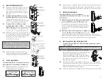
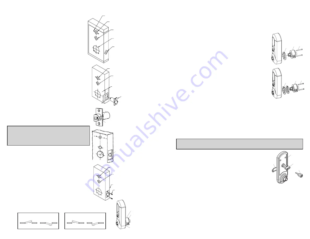
Place paper template (supplied) onto door
and mark for holes. Drill the four
1
⁄
4
" (7
mm) holes first. Next drill the 2
1
⁄
8
" (54
mm) cross bore hole. Drill the 1" (25 mm)
hole last.
A-2
For Models 5041 & 5051 only. When
installing Model 5021, skip to step A-4
.
Passage feature models require an
additional 1” (25 mm) hole in the door face
(see “a” in the illustration to the right).
A-3
For Models 5031 & 5051 only. When
installing Models 5021 or 5041
models,
skip to step A-4
. Inside code change models
require an additional 1” (25 mm) hole in the
door face (see “b” in the illustration above).
A-4
Mortise door edge for latch unit faceplate (c)
1
⁄
8
" (3 mm) deep to dimensions shown. Insert
latch unit into the 1" (25 mm) hole, making
certain that the latch bolt bevel faces
direction of closing door.
Note
: If using a
3
⁄
4
" (19 mm) latch, the edge of the
latch bore hole must be prepped to accomodate
the anti-friction hinge. (The location of the anti-
friction hinge depends on the door handing).
A-5
Secure the latch to the door using two
3
⁄
4
"
(19 mm) combination screws (d) supplied.
Latch unit faceplate must be flush with door (e).
B.
LOCK HANDING
The Simplex 5000 is a non-handed lock that is
preassembled for left-hand door installations.
B-1
Determine the hand of your door. For left
hand doors, proceed to Section C.
For right hand doors, follow steps in B-2.
2
4 x
1
⁄
4
"
b 1" (for models
5031 & 5051)
a 1" (for models
5041 & 5051)
b 1" (for models
5031 & 5051)
Mortise approx.
5
⁄
16
" (8 mm)
extra depth to
allow clearance
of anti-friction
hinge
b 1" (for models
5031 & 5051)
a 1" (for models
5041 & 5051)
a 1" (for models
5041 & 5051)
2
1
⁄
8
"
1"
1
1
⁄
8
"
c
Anti-friction hinge
Anti-friction device
e
d
2
1
⁄
4
"
3
B-2
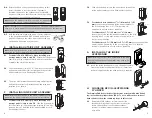
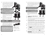
Remove the two connecting screws (a) from the cylindrical drive unit (b).
Rotate cylindrical drive unit 180 degrees. Reposition spacer (c) as found
before disassembly. Remount drive unit with the two connecting screws.
C.
DOOR THICKNESS
The Simplex 5000 lock is preassembled to
accommodate standard door thickness 1
5
⁄
8
" (41 mm)
to 2" (51 mm).
C-1 (Reference Figure A) For thinner door applications
of 1
3
⁄
8
" (35 mm) to 1
1
⁄
2
" (38 mm)
Remove and
discard the two connecting screws (a) from the
cylindrical drive unit (b). Remove and discard the
spacer (c). Remount the cylindrical drive unit using
the two shorter 1
3
⁄
8
" (35 mm) connecting screws
supplied.
C-2 (Reference Figure B) For thicker door applications
of 2
1
⁄
8
" (54mm) to 2
1
⁄
4
" (57mm)
Remove the two
connecting screws (a) from thecylindrical drive unit (b). Add the extra
spacer(c) supplied. Remount the cylindrical drive unitusing the same two
connecting screws (a) just removed. (Do not over tighten screws)
D.
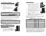
INSTALLING THE PASSAGE SET
For models 5041 & 5051 only. When installing non-passage models,
skip to section E.
Note:
The end user may choose either a key cylinder (a) or turn knob (b)
actuator to engage the passage function.
D-1
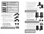
Prior to installing the passage actuator, hold the
chosen actuator housing in one hand, and with the
other hand, rotate the key cylinder or knob
counterclockwise until it stops. If the key cylinder
actuator is used, withdraw the key, which will lock
the cylinder in this position (a detent in the turn
knob locks the cylinder).
D-2
Insert the key cylinder or turn knob assembly (a or b) into the opening
on the inside unit assembly (c). Upon completion, the arrow of the turn
knob should be pointing to the left, or the dot on the face of the key
cylinder actuator should be on the left.
D-3
Secure the passage set assembly with the spring clip (d) from the inside.
Left Hand
Left Hand Reverse Bevel
R
LEFT HAND DOOR
Right Hand
Right Hand Reverse Bevel
RIGHT HAND DOOR
L
c
a
b
b
a
c
b
a
c
c
b
d
a
Summary of Contents for Simplex 5000 Series
Page 12: ...19 18 Notes Notes ...


