5
F-2
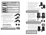
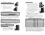
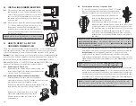
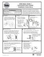
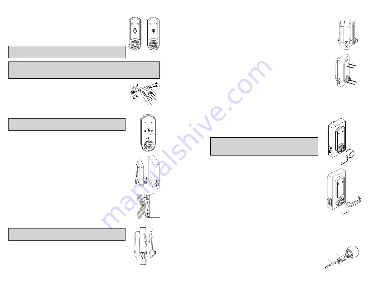
Slide the drive hub (a) into the drive sleeve (b) until the
inside unit assembly (c) rests flush against the door.
F-3
For standard door thickness 1
5
⁄
8
" (41 mm) to 2" (51
mm),
secure the outside and inside unit assemblies to
the door by using four 2
7
⁄
8
" (73 mm) screws (d)
(supplied) in all four holes as indicated.
For thinner door 1
3
⁄
8
" (35 mm) to 1
1
⁄
2
" (38 mm),
secure the outside and inside unit assemblies to the door
by using four 2
1
⁄
2
" (64 mm) screws (e) (supplied) in all
four holes as indicated.
For thicker door 2
1
⁄
8
" (54 mm) to 2
1
⁄
4
" (57 mm),
secure the outside
and inside unit assemblies to the door by using four 3
1
⁄
4
" (82mm)
screws (f) (supplied) in all four holes as indicated.
G.
INSTALLING THE INSIDE
LEVER/KNOB
Note:
Installing the lever/knob assemblies to the unit
before mounting the unit assemblies, may ease initial
installation.
G-1
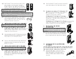
Insert the inside lever/knob (a) onto the unit assembly.
Secure the inside lever/knob with the
3
⁄
8
" (5mm) hex
screw (b) supplied using the allen wrench (c) supplied.
H.
CHANGING KEY-IN-LEVER/KNOB
CYLINDER
The Simplex 5000 outside lever/knob comes preassembled with Kaba's
key-in-lever/knob cylinder (Kaba 1599). To use a different key-in-lever/
knob cylinder, follow the remaining steps in this section.
H-1
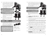
Remove KIL/KIK cylinder (a) from the outside
lever/knob (b) by removing the lever insert (e) (no
insert on knob). Remove the rubber cylinder
retainer (c) using a small screwdriver or needle
nose pliers.
4
D-4
Rotate the knob or key cylinder (re-insert key at this
point) clockwise to test the rotation. If properly
installed, the knob or key cylinder should rotate 90
degrees clockwise so that the arrow (knob) is pointing
up or the dot (key cylinder) is at the top.
Note:
Leave the actuator set in this position for installation
(if key cylinder is used, remove the key at this point).
Note:
The tailpiece of the passage actuator is scored on several places to
allow you to easily break off the section that extends beyond the required
length to engage the passage set cam.
D-5
Hold the tailpiece firmly with a pair of pliers, adjacent
to the desired break line. With a second pair of pliers,
grip the tailpiece on the other side of the scored line
and bend up and down until it breaks.
E.
INSTALLING OUTSIDE UNIT ASSEMBLY
Note:
Installing levers/knobs to the unit assemblies before
mounting the unit assemblies may ease initial installation.
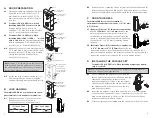
E-1
For models 5041 & 5051 only. When installing non-
passage models, skip to step E-2
. Ensure that the passage
cam (b) is rotated counterclockwise until it stops. When
complete, the slot will be vertical.
E-2
Slide the drive unit (a) into 2
1
⁄
8
" (54 mm) cross bore hole
by depressing latch bolt (b) in slightly until the outside
unit assembly (c) rests flush against the door.
E-3
The drive unit (d) must engage the latch unit prongs (e)
and the shoe retractor (f) must engage the latch unit
tailpiece (g) as shown.
F.
INSTALLING INSIDE UNIT ASSEMBLY
Note:
Installing levers/knobs to the unit assemblies before
mounting the unit assemblies may ease initial installation.
F-1
For Models 5041 & 5051 only. When installing non-
passage models, skip to step F-2
. Slide the drive hub (a)
into the sleeve (b), and the passage tailpiece (d) into the
passage cam slot until the inside unit assembly (c) rests
flush against the door.
b
f
g
e
d
c
a
b
c
d
a
b
c
a
b
d, e, f
c
a
b
c
a
b
b
a
d
c
Summary of Contents for Simplex 5000 Series
Page 12: ...19 18 Notes Notes ...


