9
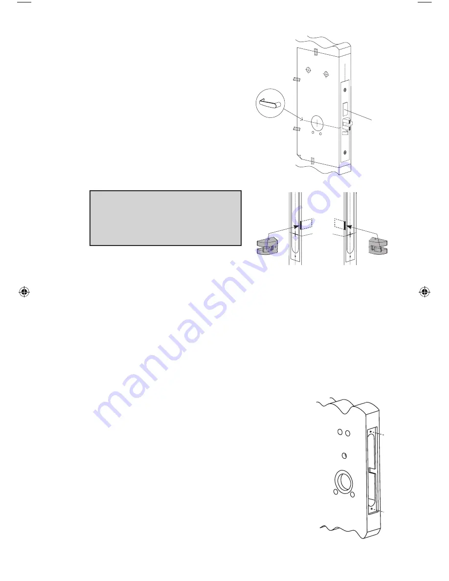
The axis of rotation of the handle is level
with the bottom lip of the strike.
B-2
Align the template along the vertical
center line of the mortise (CL) at the
desired handle height, and tape it to
the door.
B-3
Mark all holes and cutouts for the
mortise in the edge of the door and
remove the template.
B-4
Locate the two sets of vertical fold
lines on the template allowing you
to adjust the positioning of the tem-
plate depending on the bevel of the
door.
Note: Fold lines on template are for
1
3
⁄
4
” door. Some thickness and bevel
conditions may make it necessary to
re-position the template for marking
each side of the door.
B-5
If the door has no bevel, fold the template along the solid lines. Align the
fold with the edge of the door and mark the holes for the lock. Repeat on
the other side of the door. If the door has a 3° bevel, fold and align the
dashed line marked “H” on the template with the higher-beveled edge of
the door and mark the lock holes on that side of the door. Repeat on the
side with the lower-beveled edge using the dashed line marked “L.”
B-6
Prepare the cutout for the mortise in the edge of the door using a mortis-
ing machine, router and chisel (for dimensions, refer to template). Ensure
clearance is provided for moving latch parts as
indicated on the template.
B-7
When making holes, drill from both sides of the
door to prevent unsightly damage (for dimensions,
refer to template). Drill the small holes before the
large holes. This will keep small holes on location
before the 2
1
⁄
8
“ holes are made tangent with them.
Mortise
RH/LHR (ASM shown) LH/RHR
Handle
Height
LIT1051_Simplex_506x _Mortise_1012.indd 9
1/7/13 3:13 PM
Summary of Contents for Simplex 506 Series
Page 1: ...Simplex 506x Mortise Installation Instructions ...
Page 15: ...15 Notes ...


