5
4
C. DRILLING HOLES IN THE DOOR
CAUTION:
Positioning and drilling must be done straight to ensure trouble
free operation of the model 7106 lockset. Improper drilling may result in
excessive force being exerted on the lock which may result in the premature
wearing of its mechanical parts.
You must do Step 1 first or it will be impossible to drill the four
1
⁄
4
" (6 mm)
holes.
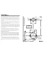
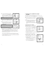
C-1
Use a
1
⁄
4
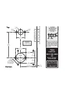
" (6 mm) drill bit to drill the four holes for the thru-bolts
(See A in
Figure 3-1)
. To prevent splintering the door or breaking the drill bit, begin
drilling at a slow speed and increase the speed gradually until the tip of
the drill bit emerges from the other side of the door. Repeat this proce-
dure from the opposite side of the door.
C-2
Use a hole saw with pilot bit to make the 1
3
⁄
8
" (35 mm) hole (B). Apply
pressure evenly until the circular blade cuts
the first side of the door and the tip of the
pilot bit emerges through the other side, then
stop. Drill from the other side until the 1
3
⁄
8
"
(35 mm) hole is completed.
C-3
Repeat Step C-2 for the
3
⁄
4
" (19 mm) hole
(See C in Figure 3-1)
.
C-4
Drill the four
1
⁄
8
" (3 mm) holes
3
⁄
4
" (19 mm)
deep
(See D in Figure 3-1)
.
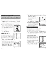
D. ADJUSTING THE LOCK
The lock has been pre-assembled to accommodate
doors up to 2
1
⁄
4
" (57 mm) thick. If your door is 1
3
⁄
8
" to 2" (35 mm to 51 mm) thick, you must short-
en both tailpieces
X
and
Y (See Figure 4-1)
and
shorten the (
A
) Two thru-bolts used to secure the
(
B
) combination change assembly.
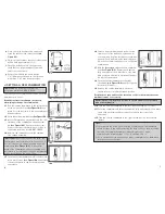
D-1
Shorten the combination change tailpiece
X
according to your door thickness. Tailpiece
X
has been pre-marked for various door
thicknesses for accuracy and convenience.
a)
After determining the break line, hold the
tailpiece firmly with a pair of pliers on the lock
side of the tailpiece, just beside the desired
break line.
b)
With a second pair of pliers, grip the tail
piece at the other side of the line and bend it
up and down until it breaks
(See Figure 4-2)
.
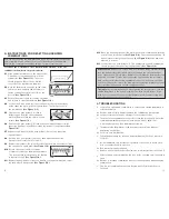
D-2
While holding the lockset firmly against the outside of the door,
(See
Figure 4-1)
mark tailpiece
Y
at the point where it extends
1
⁄
2
" -
5
⁄
8
" beyond
the interior surface of the door.
a)
After determining the break line, hold the
tailpiece firmly with a pair of pliers on the
lock side of the tailpiece, just beside the
desired break line.
b)
With a second pair of pliers, grip the tail
piece at the other side of the line and bend it
up and down until it breaks
(See Figure 4-2)
.
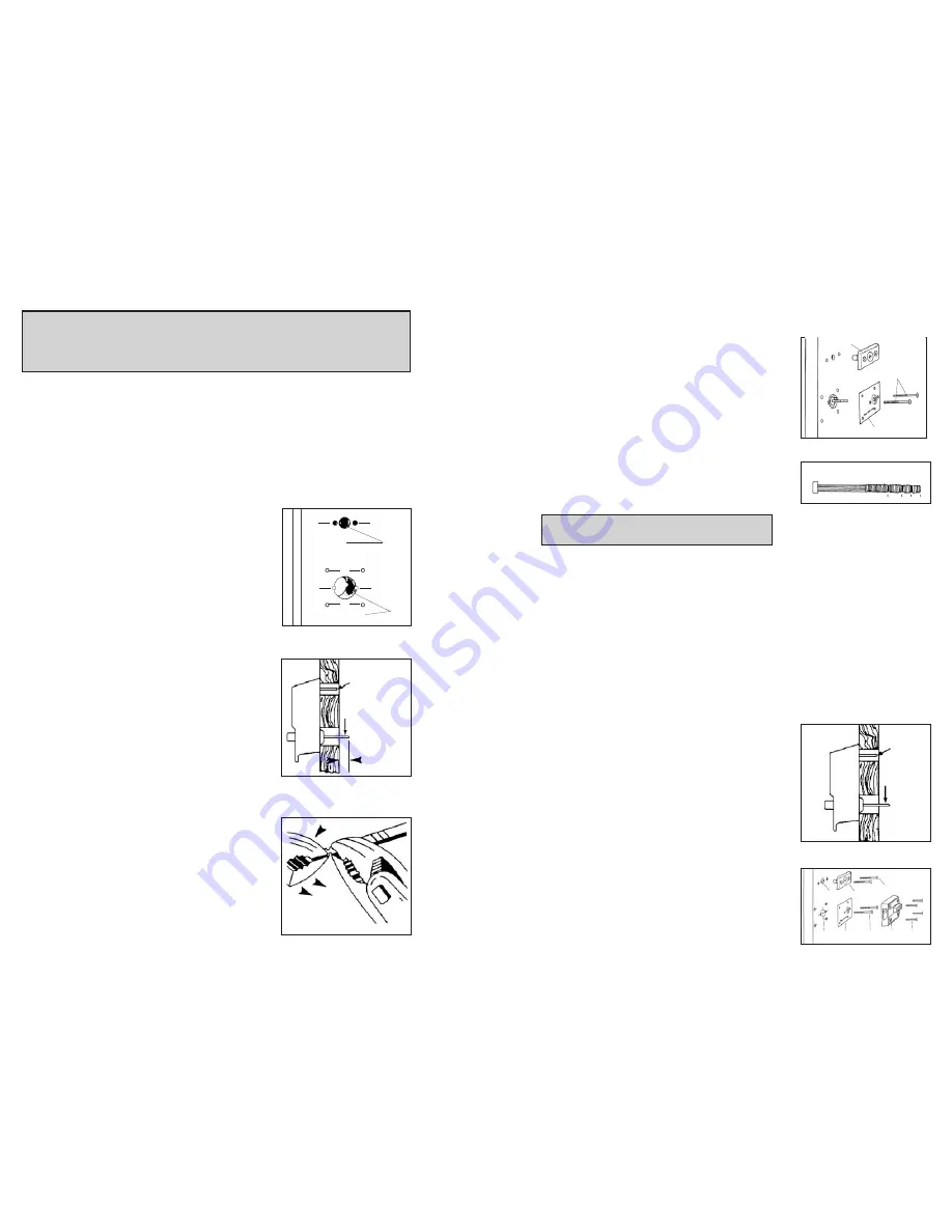
D-3
Shorten each of the two reinforcing plate thru-
bolts (A)
(See Figure 4-3)
by gripping
at the threaded end with pliers and sawing
through, at the correct length
(See Figure
4-4)
, with a fine-tooth hacksaw.
Note
: Be careful not to damage the threads
when shortening the thru-bolts.
• For 1
3
⁄
8
” (35 mm) thickness doors, shorten thru-bolt at
A
.
• For 1
3
⁄
4
” (45 mm) thickness doors, shorten thru-bolt at
B
.
• For 2” (51 mm) thickness doors, shorten thru-bolt at
C
.
• For 2
1
⁄
4
” (35 mm) thickness doors, leave thru-bolt as is.
D-4
To secure (B) combination change assembly
(See “G” Figure 5-2)
, utilize
two 2" (51 mm) bolts (H) for door thickness 1
3
⁄
8
" (35 mm) to 1
1
⁄
2
" (38 mm).
For door thickness 1
1
⁄
2
" - 2" utilize two 2
3
⁄
8
" (60 mm) bolts (H). For door
thickness 2" - 2
1
⁄
4
", utilize two 3" thru-bolts (H).
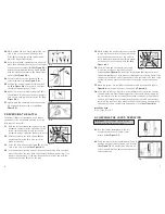
E. INSTALLING THE LOCK
The model 7106 lock is packaged for an inward
opening door. For an outward opening door, the
latch must be reversed
(See Section F)
.
Figures 5-1
(outside of door) and
5-2
(inside of
door) show how the lock is installed and identify
each component by letter. Refer to these figures
as you follow the steps below.
E-1
Insert tailpiece (
Y
) into the 1
3
⁄
8
" (35 mm) cutout
(
A
) and the combination change tailpiece (
X
)
into the
3
⁄
4
" (19 mm) hole (
B
)
(See Figure 5-1
and 5-2).
4-1
4-2
1
⁄
2
" -
5
⁄
8
"
(13 mm -
16 mm)
1st
2nd
B
C
4-3
A
5-1
4-4
A
B
C D
3
⁄
4
" (19 mm)
1
3
⁄
8
" (35 mm)
D
A
B
X
Y
X
Y
C
A
A
A
D
3-1
5-2
A
C
D
E
F
B
G
H


