6
D.
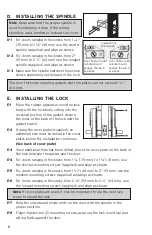
INSTALLING THE SPINDLE
D-1
For doors ranging in thickness from 1
3
⁄
8
"
(35 mm) to 1
7
⁄
8
" (48 mm) use the shorter
spindle (supplied) and align as shown.
D-2
For doors ranging in thickness from 2"
(51 mm) to 2
1
⁄
2
” (64 mm) use the longest
spindle (supplied) and align as shown.
D-3
Make sure the spindle matches the picture
shown depending on the hand of the lock.
E.
INSTALLING THE LOCK
E-1
Place the rubber gaskets around the lock
body with the lock body sitting into the
recessed portion of the gasket. Assure
the holes in the back of the lock and the
gasket match.
E-2
If using the cover plates (supplied), an
additional hole must be drilled in the cover
plates before the installation continues
(See back of cover plate)
.
E-3
Once additional hole has been drilled, place the cover plate on the back of
the lock between the gasket and the door.
E-4
For doors ranging in thickness from 1
3
⁄
8
”( 35 mm) to 1
5
⁄
8
”( 41 mm), use
the shorter mounting screws (supplied) and align as shown
E-5
For doors ranging in thickness from 1
3
⁄
4
" (44 mm) to 2” (51 mm), use the
medium mounting screws (supplied) and align as shown.
E-6
For doors ranging in thickness from 2
1
⁄
8
" (54 mm) to 2
1
⁄
2
” (64 mm), use
the longest mounting screws (supplied) and align as shown.
Note
: If cover plates are used, it may be necessary to use the next size
screw to mount the lock.
E-7
Hold the outside and inside units on the door with the spindle in the
proper position.
E-8
Finger-tighten the (2) mounting screws, assuring the lock is vertical and
sitting flush against the door.
Viewed from
the outside
Door hung on right
spindle should
engage the latch
as above
Door hung on left
spindle should
engage the latch
as above
Note
: Assurance that the proper spindle is
used is extremely critical. If the wrong
spindle is used, binding or lockout can occur.
The door thickness including gaskets and trim plates can not exceed 2
1
⁄
2
"
(64 mm).


