background image

A

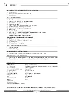
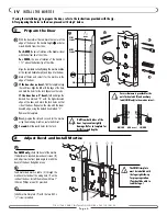
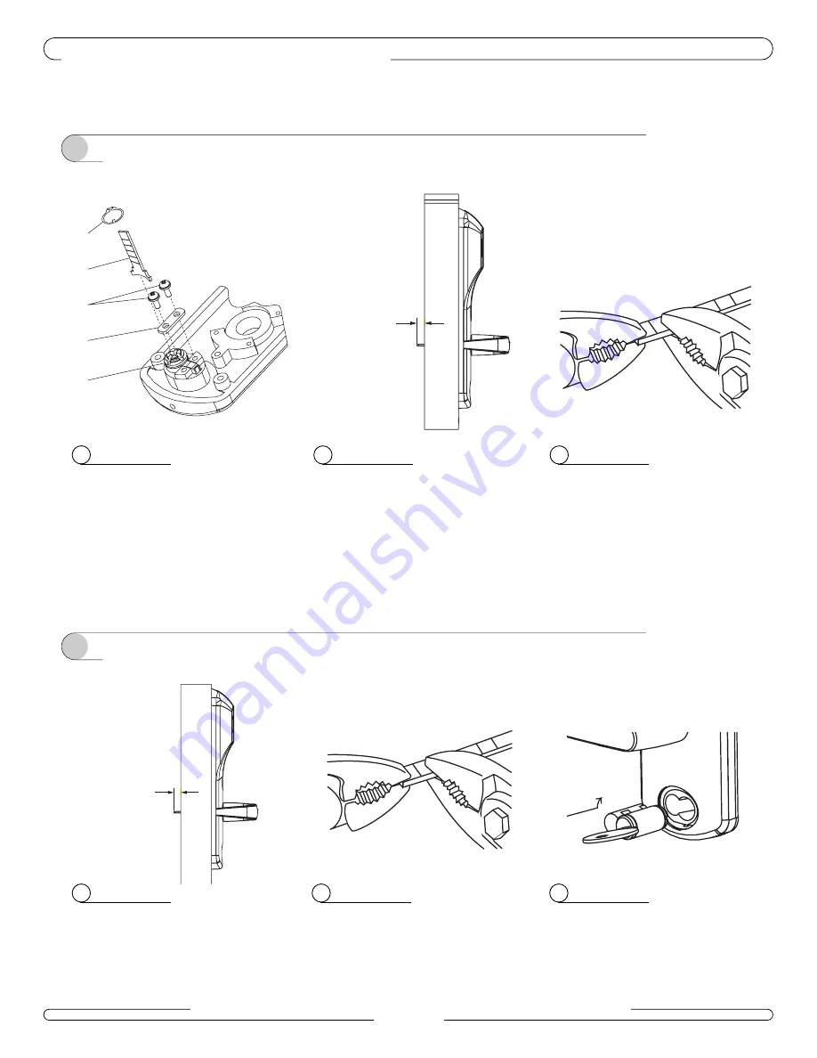
Assemble the key cylinder (D) in the rear of the
outside housing, and secure it using the bridge
(E) and two 8-32 x 

9

/

16

” (14mm) Phillips

screws (F).

Install the tailpiece (G) horizontally in the cylin-
der, and secure it with the retaining clip (W),
using an external ring plier.

C

Break off the tailpiece at the mark using two
pairs of pliers.

B

Hold the outside housing against the door. The
tailpiece should extend between

1

/

4

” and 

5

/

8

beyond the rear face of the door. Mark the tail-
piece accordingly.

V  

PREPARE THE MECHANICAL OVERRIDE

7 1 0 - I I / 7 4 0   S E R I E S   I N S TA L L AT I O N   G U I D E   •   P K 2 7 1 0 / 0 8 / 0 2

P a g e   7

2

Removable Core Cylinder Mechanical Override

1

Key-in-Knob Mechanical Override

If you have an electrical override lock, continue on page 8.

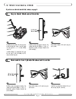
A

Hold the outside housing against the door. The
tailpiece should extend between

1

/

4

” and 

5

/

8

beyond the rear face of the door. Mark the tail-
piece accordingly.

B

Break off the tailpiece at the mark using two
pairs of pliers.

C

Install the key cylinder from the front of the out-
side housing, using the control key.  

1

/

4

” to 

5

/

8

” 

(6.3 to 16mm)

W

G

F

E

D

1

/

4

” to 

5

/

8

” 

(6.3 to 16mm)

Summary of Contents for Solitaire 710-II Series

Page 1: ...INSTALLATION GUIDE Solitaire 710 II and SMART 740 Series AMM and AADB Models PK2710 T...

Page 2: ...lpiece retaining clip Tools in spare parts box not illustrated 5 64 hex Allen key 1 8 hex Allen key Packaged separately with lock shipment T Override cylinder mechanical core and removable core overri...

Page 3: ...710 II 740 SERIES INSTALLATION GUIDE PK2710 08 02 Page 3 A D E K T H I Q J K B G B1 B2 F G P O P F C R N M L S...

Page 4: ...ed Mortise Technical Assistance For technical assistance call 1 800 906 4526 Warnings and Cautions II INTRODUCTION AND DISCLAIMERS 710 II 740 SERIES INSTALLATION GUIDE PK2710 08 02 Page 4 Please read...

Page 5: ...optional for wood door frames required for metal door frames and check the strike handing on the template Install the strike using the screws provided 1 Mark the Location of the Strike 2 Prepare the...

Page 6: ...Repeat on the side with the lower beveled edge using the dashed line marked L Remove the template First prepare the slot and cut outs for the mortise using the mortising machine router and chisel Sec...

Page 7: ...of the door Mark the tail piece accordingly V PREPARE THE MECHANICAL OVERRIDE 710 II 740 SERIES INSTALLATION GUIDE PK2710 08 02 Page 7 2 Removable Core Cylinder Mechanical Override 1 Key in Knob Mech...

Page 8: ...ws Q on the bottom right and top left of the inside housing 12 Turn the outside lever and then the inside lever to ensure that the bolt retracts 13 For mechanical override models the override key has...

Page 9: ...ntinuously Reset the electronics by disconnecting the battery pack for ten seconds then reconnect it 18 Install the medallion A on the outside housing and secure it using the 5 64 hex head screw C On...

Page 10: ...anding If the lever feels tight hard to turn or does not return easily to its horizontal rest position check the alignment of the lock assemblies Loosen the mounting screws and shift the outside housi...

Page 11: ...extend the deadbolt On autodeadbolt models the dead bolt should have extended when the door was closed Open the door by turning the lever The deadbolt and the latch bolt retract simultaneously and fu...

Page 12: ...ntr al QC H4P 2G7 Technical Support 1 800 906 4526 Customer Service T 1 877 468 3555 F 514 735 6589 General Information www kabalodging com Online Consumable Orders www keycard com To access all of ou...

Reviews: