background image


2020 

080x.000.01.01.01 

25 


6.2.2 

MATBOI 480 T / 650 T 


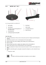
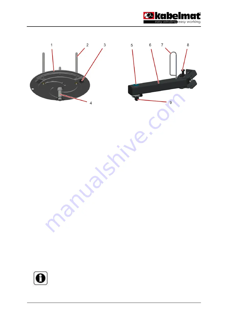
Fig. 17 Adjusting MATBOI 480 T and MATBOI 650 T 
 

Bearing plate 

Clamping bolt 

Knurled screw for central adjustment of 
the clamping bolts 

Connecting shaft 

Locating bearing for bearing plate 


Bearing arm 

Cable routing 

Locking bolt swivel arm 

Star knob brake 


Insert ring collar 

►  Loosen the safety bolt on the swivel arm and swivel the swivel arm outwards until the safety bolt 

engages. 

►  Loosen the knurled screw of the central adjustment of the clamping bolts. 

►  At the knurled screw, push the clamping bolts inwards via the central adjustment 

►  Insert ring collar. 

►  At the knurled screw, push the clamping bolts outwards via the central adjustment. 

►  Tighten the knurled screw of the central adjustment of the clamping bolts. 

►  Loosen the safety bolt on the swivel arm and swivel the swivel arm inwards until the safety bolt en-

gages. 

►  Guide the material through the cable guide and adjust the braking force on the star knob if neces-

sary. 

  Ring collar is inlaid 


Info 

If material runs off during unwinding, the braking force must be adjusted. 


Summary of Contents for MATBOI 200 T

Page 1: ...MATBOI SPULBOI TRANSLATION OF THE ORIGINAL OPERATING MANUAL Winding Unwinding Wrapping Measuring Cables Wires Ropes Pipes Hoses Manual coil and spool storage system...

Page 2: ...ee that the specifications are cor rect and complete We reserve the right to make technical changes due to advancements All rights reserved especially the rights to duplication dissemination and trans...

Page 3: ...cessories 11 3 3 1 MATBOI coil bearing 11 3 3 1 1 MATBOI 200 T 11 3 3 1 2 MATBOI 300 T 11 3 3 1 3 MATBOI 450 T 12 3 3 1 4 MATBOI 480 T left right 12 3 3 1 5 MATBOI 650 T left right 13 3 3 2 SPULBOI sp...

Page 4: ...6 Operation 23 6 1 Setting 23 6 1 1 MATBOI 480 T and MATBOI 650 T pop up protection 23 6 2 Adjusting 24 6 2 1 MATBOI 200 T 300 T 450 T 24 6 2 2 MATBOI 480 T 650 T 25 6 2 3 SPULBOI 200 4 S 300 3 S 450...

Page 5: ...ents The following documents are considered other applicable documents 1 2 Storage location Always store this technical document and all other applicable documents within reach and accessible for late...

Page 6: ...vented CAUTION Indicates a dangerous situation that may lead to injury if not prevented NOTE Indicates a situation that may lead to property damage if not prevented Tab 1 Signal words The following pi...

Page 7: ...than one work step are structured as follows Purpose of action optional 1 Instruction Result of action instruction 1 optional 2 Instruction Result of action instruction 2 optional Result of action op...

Page 8: ...f the material must be observed Depending on the equipment cable coils and or cable spools can be stored ready for removal If a product is equipped for special applications it is only designed to meas...

Page 9: ...th lockable swivel castors The storage system can be equipped with different braked bearing plates and spools and can thus be individually adapted see Chap 4 Technical data 3 1 Layout Fig 1 Example co...

Page 10: ...are used to hold the various bearing arrangements The storage rack is equipped with lockable swivel castors for mobile use MATBOI coil bearing MATBOI coil bearings are used for cable coils hoses and p...

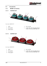
Page 11: ...Shelf 2 Bearing plate 3 Clamping bolt 4 Clip on holder 5 Unwind brake with cable guide and pos sibility of mounting the MESSBOI 10 H 3 3 1 2 MATBOI 300 T Fig 3 Layout of MATBOI 300 T 1 Shelf 2 Bearin...

Page 12: ...te 3 Clamping bolt 4 Clip on holder 5 Unwind brake with cable guide and pos sibility of mounting the MESSBOI 10 H 3 3 1 4 MATBOI 480 T left right Optionally available with pop up protection Fig 5 Layo...

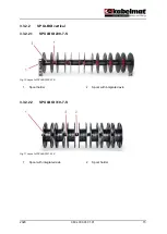
Page 13: ...ction Fig 6 Layout of MATBOI 650 T 1 Bearing plate 2 Bearing arm 3 3 2 SPULBOI spool bearing 3 3 2 1 SPULBOI horizontal 3 3 2 1 1 SPULBOI 200 4 S Fig 7 Layout of SPULBOI 200 4 S 1 Shelf 2 Bearing plat...

Page 14: ...f 2 Bearing plate 3 Centring piece 4 Unwind brake with cable guide and pos sibility of mounting the MESSBOI 10 H 3 3 2 1 3 SPULBOI 450 2 S Fig 9 Layout of SPULBOI 450 2 S 1 Shelf 2 Bearing plate 3 Cen...

Page 15: ...3 2 2 SPULBOI vertical 3 3 2 2 1 SPULBOI 200 7 S Fig 10 Layout of SPULBOI 200 7 S 1 Spool holder 2 Spool with integrated axle 3 3 2 2 2 SPULBOI 310 7 S Fig 11 Layout of SPULBOI 310 7 S 1 Spool with in...

Page 16: ...20 080x 000 01 01 01 16 3 3 2 2 3 SPULBOI 310 4 S Fig 12 Layout of SPULBOI 310 4 S 1 Spool 2 Axle 3 Axle support 3 3 2 2 4 SPULBOI 310 5 S Fig 13 Layout of SPULBOI 200 5 S 1 Spool 2 Axle support 3 Axl...

Page 17: ...2020 080x 000 01 01 01 17 3 3 2 2 5 Cable guide rail Fig 14 Layout of cable guide rail 1 Cable guide rail 2 MESSBOI 10 optional...

Page 18: ...700 mm Load lifting capacity max 200 mm Weight approx 42 kg Tab 5 MATBOI SPULBOI base frame Attachment for storage rack H x W x D approx 60 x 30 x 315 mm Tab 6 Accessories MATBOI SPULBOI attachment fo...

Page 19: ...rm version left right left right Plate 480 mm 480 mm 650 mm 650 mm Coil max 470 mm max 470 mm max 640 mm max 640 mm Height of core bolt 250 mm 250mm 250 mm 250 mm Core adjustment range 140 320 mm 140...

Page 20: ...horizontal spool bearing SPULBOI 200 7 S SPULBOI 310 7 S Number of spools 7 7 Spool 150 200 mm 310 mm Spool width 75 80 mm 75 mm Core 140 320 mm 140 320 mm Spool weight max 4 kg max 5 kg Tab 12 Acces...

Page 21: ...ies empty spools 4 4 Measuring devices MESSBOI 10 H MESSBOI 10 LS Measuring range 1 15 mm 1 15 mm Measuring force Spring pressure Spring pressure L x W x H approx 260 x 110 x 140 mm approx 260 x 110 x...

Page 22: ...range is between 5 C and 40 C with maximum non condensing air humidity of 80 The owner must secure the space around the device according to applicable regulations 5 3 Storage Do the following work bef...

Page 23: ...ng the pop up protection Loosen the safety bolt on the swivel arm and swivel the swivel arm outwards until the safety bolt engages Release the star knob brake Remove the bearing plate Attach the pop u...

Page 24: ...bolts Insert ring collar Press the clamping part of the clip on holder upwards and pull off the clip on holder Use the tensioning spanner to push the clamping bolts inwards via the central adjustment...

Page 25: ...ages Loosen the knurled screw of the central adjustment of the clamping bolts At the knurled screw push the clamping bolts inwards via the central adjustment Insert ring collar At the knurled screw pu...

Page 26: ...r brake force regula tion Insert spool Loosen the wing screw Remove the centring piece Insert the spool Push the centring piece onto the mandrel until the spool is fixed Tighten the wing screw Guide t...

Page 27: ...ith integrated axle Remove and insert spool Push the spool to the left into the axle receptacle and remove it Spool is removed Push the spool with the narrow axle side into the left axle receptacle an...

Page 28: ...4 S and SPULBOI 310 5 S 1 Spool 2 Axle 3 Axle support Insert spools Lift the axle out of the axle holders Push the spools onto the axle and distribute them Place the axle with spools in the axle holde...

Page 29: ...00 T and MATBOI 450 T Item Designation Item number 1 Brake with bearing size H 200 Brake with bearing size H 300 Brake with bearing size H 450 0107 06 0101 0108 02 0101 0108 02 0101 2 Clip on holder w...

Page 30: ...SPULBOI 200 4 S SPULBOI 300 3 S and SPULBOI 450 2 S Item Designation Item number 4 Brake with bearing size H 200 Brake with bearing size H 300 Brake with bearing size H 450 0107 06 0101 0108 02 0101 0...

Page 31: ...31 8 Customer service If you require customer service please contact the following address Kabelmat Wickeltechnik GmbH Steinbuckelweg 25 D 72293 Glatten Tel 49 74 43 96 70 0 Fax 49 74 43 96 70 39 E ma...

Page 32: ...xx Describe the reason for change in detail providing the page number and the affected paragraph or chapter Text content xxxx xxx xx xx xx Images xxxx xxx xx xx xx Orthography Appearance xxxx xxx xx...

Reviews: