background image


4.1.3 Flue gas extraction 


GENERAL


Flue gas extraction is an essential part of your heating installation.   Well-assembled flue gas extraction 
considerably  extends  the  working  life  of  your  heating  boiler  and  has  a  positive  effect  on  heating 
efficiency. 


Warning:


Because in most cases the flue gas temperature is higher than 180 °C, it is the desirable to 

insulate  the  outlet  with  heat-resistant  material  in  places  where  contact  with 
body parts is possible. These are available from Kabola Heating Systems B.V. 


  Ensure the correct length/diameter proportions. We advise assembling a flue gas outlet with a 

diameter of 50 mm and a maximum length of 3 metres. 

  On sailing and seagoing vessels we advise using a vertical flue gas discharge system (see fig 5). 


AUTOMOTIVE APPLICATION


With the installation of the heating system for an application not for use on water, one can decide to 
keep the flue gas outlet as short as possible. 


HORIZONTAL OUTLET WITH SKIN FITTING


It is possible to bring the flue gas outlet horizontally from the boiler through the wall. The following 
points must then be respected: 


  The maximum permitted length without bends is 3 metres. 

  Make sure that the outlet is amply above the water level. If this is not possible use a curved 

construction (a swan neck as pictured on the right in figure 4). 

  Use a skin fitting (single- or double-walled) to bring the flue gas outlet through the wall. 

  Use as few as possible bends, no more than 3 bends of 90 °. 


Tip:


If with the existing assembled flue gas outlet you have a larger diameter than 
the diameter of the flue gas outlet from the boiler, we recommend assembling 
a flexible flue gas outlet (50 mm diameter) in the existing flue gas outlet. The 
necessary  adaptors  and  auxiliary  parts  are  available  from  Kabola  Heating 
Systems B.V. 


Warning:


When using a flue gas outlet longer than prescribed it is possible that 
condensation water may originate in the outlet. It is very important that the 
condensation water does not form a water trap with the flue duct 
becoming blocked (as pictured on the left in figure 4). 


Using  a  swan  neck  (as  pictured  right  in  figure  4)  prevents  water  from 
entering the flue duct from outside. 


Figure 4


Summary of Contents for Boiler-CH

Page 1: ...1 User Guide Compact 7 series Boiler CH Calorifier Combi...

Page 2: ...ip gives the user suggestions and advice to be able to carry out certain tasks more easily Note The user is given additional information here Any potential problems are also covered Warning Chance of...

Page 3: ...ng system 7 4 1 3 Flue gas extraction 9 4 1 4 Electrical connection 11 4 1 5 Filling the central heating system for the Compact 7 central heating boiler 13 4 1 6 Connecting the oil filter 14 4 2 Bring...

Page 4: ...the space in which they are installed Heating only takes place using radiators a hot air system underfloor heating and or any custom made airco systems in which the Kabola COMPACT 7 is integrated When...

Page 5: ...COMPACT 7 boiler MEASURES FOR SAFE INSTALLATION Do not place any flammable and or gaseous substances that may cause danger of explosion or fire in the space where the boiler is or is to be installed...

Page 6: ...wing points must be observed Make sure that the casing cannot be damaged Use a blanket for example Transport the boiler upright with the base below 3 2 Storage When the boiler is to be stored for long...

Page 7: ...with bolts or tack welding Make sure there is a distance between the outlet and the wall of at least 10 20 mm because of the heat transfer from the flue gas outlet Ensure sufficient space around the b...

Page 8: ...point 1 6 Assemble the central heating return and boiler pipe at point 2 7 Assemble the boiler supply pipe at point 3 8 Assemble the separately supplied filler tap and drain combination at point 4 see...

Page 9: ...e flue gas outlet horizontally from the boiler through the wall The following points must then be respected The maximum permitted length without bends is 3 metres Make sure that the outlet is amply ab...

Page 10: ...ce The maximum permitted length with a vertical system is 5 meters With a vertical outlet always use a drain Figure 5 Tip Kabola can manufacture a deck hole at an angle so the flue is straight as cust...

Page 11: ...er Tip If you use a transformer we advise using a 900W sine wave transformer Do not place the room thermostat near a heat source Figure 6 Compact 7 central heating boiler Connection of the room thermo...

Page 12: ...the plug see fig 11 Connect the wires for the hot water on off function to points S3 and B4 as shown on the sticker on the plug frostguard see fig 11 The two boiler thermostat wires only need to be c...

Page 13: ...n off switch button lights Put the heating pump in automatic venting position Control knob to 12 hours see Figure 9 Turn a quarter of a turn the red button after about 5 minutes to position 3 see Figu...

Page 14: ...e oil filter no branch point for other oil users Connect the two oil hoses from the burner to the oil filter Note the arrows Make sure that the arrow directions of the oil pump and the oil filter corr...

Page 15: ...grees higher than the ambient temperature also see the room thermostat manual Open the fuel tank valve Open the oil filter valve by turning the red button to the left fully open If the red failure oil...

Page 16: ...ime Circulation pump operates for 3 minutes The figure 19 on the right of the display shows the current boiler water temperature 5 Operation Compact 7 CH Operating panel Compact 7 CH front Figure 15 1...

Page 17: ...ning time 0 seconds Flashing point hot water off Point lit up hot water stand by The figure 19 on the right of the display shows the current boiler water temperature Compact 7 Calorifier Operating pan...

Page 18: ...Tap comfort position Boiler kept at temperature Flashing point hot water off Point lit up hot water stand by The figure 19 on the right of the display shows the current boiler water temperature Compac...

Page 19: ...nside of the boiler using a pipe cleaner Note Do not use any aggressive cleaning products when cleaning 1 5 Suck the heating boiler empty with a vacuum cleaner 1 6 Replace the boiler gasket 1 7 Replac...

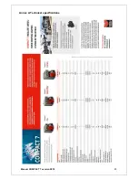
Page 20: ...Annex A Technical specifications Manual COMPACT 7 version 2018 20...

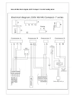
Page 21: ...Annex B Electrical diagram 230 V Compact 7 central heating boiler...

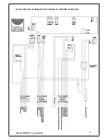
Page 22: ...22 Manual COMPACT 7 version 2018 Annex C Electrical diagram 230 V Compact 7 Calorifier and Combi...

Page 23: ...t the oil filter Burner failure Voltage too low Check voltage level Nozzle defect Replace the nozzle Boiler does not respond to room thermostat Room thermostat battery is flat Replace the battery Room...

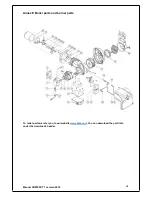
Page 24: ...24 Manual COMPACT 7 version 2018 Annex E Boiler parts and burner parts To order parts we refer you to our website www kabola nl You can download the part lists under the downloads header...

Page 25: ...25...

Page 26: ...sponsibility that the product Boiler burner Kabola COMPACT 230 V to which this declaration relates conforms with the following standards EN 303 1 EN 303 2 EN 304 EN 50081 1 EN 50082 1 EN 61010 accordi...

Page 27: ...Annex G Warranty Conditions 27...

Reviews: