background image

KABtronics                                                    

S C H E M A T I C  

World Clock Kit                                                                                                           Page 33 

Top Side Copper 


Bottom Side Copper   

Silk Screen 

Schematic 

Summary of Contents for World Clock

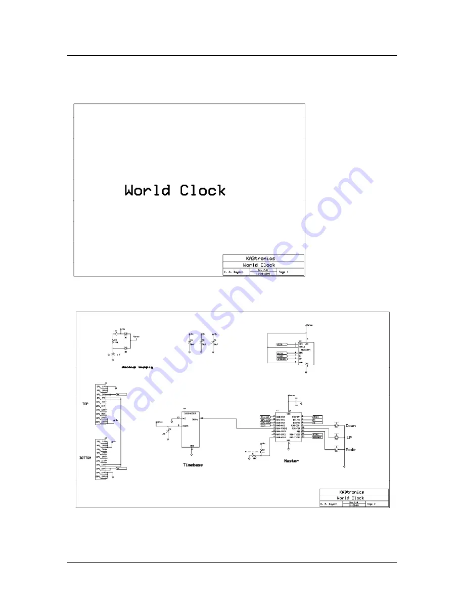
Page 1: ...World Clock Operating and Assembly Manual...

Page 2: ...LY INSTRUCTIONS DISPLAY SLICE 7 ASSEMBLY INSTRUCTIONS CONTROLLER SLICE 13 OPERATING THE WORLD CLOCK 18 PARTS IDENTIFICATION 23 THEORY OF OPERATION 29 IN CASE OF DIFFICULTY 30 SPECIFICATIONS 31 CIRCUIT...

Page 3: ...slices one controller slice and multiple display slices This manual first guides the assembly of the slices followed by operating the clock There is a section describing the parts if you are unfamilia...

Page 4: ...N P A C K I N G P A R T S L I S T World Clock Kit Page 4 Unpacking Parts List Gently unpack the contents of the box You should find one display pack for each display and one controller pack if you are...

Page 5: ...lder left on the tip helps conduct heat to the lead and the pad Insert the component leads and press the component flat against the PC Board Slightly spread the leads to hold it in place when you flip...

Page 6: ...of the solder joint don t dig into the solder joint Unsoldering A supply of de soldering braid is supplied with the kit If you find the need to remove a component use the de solder braid by pulling o...

Page 7: ...Instructions for building a display slice are first The additional instructions for building the controller slice follow One side of the PC board has white paint markings shapes and reference designa...

Page 8: ...ipping won t be mentioned again you need to do it for each part as you load it load the diode into the space marked D1 be sure to line up the white line on the diode with the white line on the board l...

Page 9: ...oad the ten 0 22 capacitors Don t load the 10uF capacitors yet they are loaded after the displays The four 7 digit displays have two decimal points these decimal points can be used to orient the displ...

Page 10: ...he flat part of the outline closer to the bottom edge Try to have the top of the LED even with the height of the display load the 14 alphanumeric displays one at a time These also have a decimal point...

Page 11: ...A B T R O N I C S A S S E M B L Y I N S T R U C T I O N S World Clock Kit Page 11 load the two 10uF capacitors They may have a small sign near the lead or they may be marked with a line as below lead...

Page 12: ...nnect with adjacent boards It is easy to get them slanted when you flip the board over and solder so be careful If you are building a display board seat the 18 pin PIC16F648 IC carefully into the IC s...

Page 13: ...a few parts to a display slice load the DS32KHZ TCXO the black block goes into the 14 pin IC labeled U2 It is missing pins 2 and 3 don t let that confuse you Have the dot towards the notch on the lef...

Page 14: ...ed try to do better You have an option for the power jack you can load it on any of the boards The only reason to consider loading it on a display board other than the controller board is to avoid hav...

Page 15: ...ttom or in the midst of the boards The boards will auto number themselves at power up starting with the board below the controller and continuing down where it wraps around to the top board and stops...

Page 16: ...troller slice Each slice sends data down to the next board Both the lowest board and the highest board need a jumper to send the signal around the chain and back to the controller The example below ha...

Page 17: ...O N I C S A S S E M B L Y I N S T R U C T I O N S World Clock Kit Page 17 Solder a small wire into the upper jumper location of the top slice and a wire jumper into the lower jumper location of the bo...

Page 18: ...Kit Page 18 Operating the World Clock In order to set up and operate this clock one needs to understand the concepts and information structure of this clock The data in the storage block persists thr...

Page 19: ...avings periods and display formats Each display has 10 settings call as a group Location Data Location name Format 12 or 24 hour Offset Hours from UTC Offset Minutes from UTC Daylight Savings Start Mo...

Page 20: ...A B T R O N I C S A S S E M B L Y I N S T R U C T I O N S World Clock Kit Page 20 The controller top level menu is shown below The key minus key and Mode key are used to navigate and operate the menu...

Page 21: ...L Y I N S T R U C T I O N S World Clock Kit Page 21 This Edit menu modifies the Location Data currently showing on the controller slice The edited settings can be stored into any display or into the...

Page 22: ...the Edit Name mode from the Edit Location Data Mode Set each character of the name and exit back to Edit Location Data Mode Step through each value of Location Data and adjust note that a 0 in the DS...

Page 23: ...23 Parts Identification Resistors Resistors can be identified by the color bands as shown in the adjacent chart These parts can be placed in either direction on the board they are not polarized Diodes...

Page 24: ...cuits These come in 18 pin 24 pin and 8 pin versions The 24 pin IC is soldered directly to the board the 8 and 18 pin ICs are placed in sockets mainly because they are reprogrammable parts and you may...

Page 25: ...ck Kit Page 25 LED Displays 16 segment LED display 7 segment LED display 7 segment display on the right and a single LED on the left The short lead goes into the square hole on the board Try to be qui...

Page 26: ...Page 26 0 027 caps 22 caps Both this and the 0 0027 cap are non polarized mount it either way 1 Farad cap This part needs to be installed carefully it is polarized Look carefully at the picture in th...

Page 27: ...D E N T I F I C A T I O N World Clock Kit Page 27 10 microfarad cap Negative side Positive side The long line identifies the positive side which need to go into the hole near the sign Switches Power...

Page 28: ...T I O N World Clock Kit Page 28 This kit has 8 pin 18 pin and 24 pin ICs Header and Connector Connector Header These are a pair of mating 20 pin right angle connectors The header goes in the top locat...

Page 29: ...Once a minute a message with the current UTC time is sent around the RS 232 signal loop described in the configuration section Each display slice holds the local time offset accounting for daylight sa...

Page 30: ...heck the jumpering o Remove any display board without a jumper to simplify the problem to the minimum number of boards This list is my guess at the cause of any problem in decreasing order of probabil...

Page 31: ...loaded for parts clearance Weight About 7 oz Power consumption About 3 7 watts 0 75 amps 5 volts DC per board Temperature limits Designed for room temperature operation 60 80 F Warrantee There is no...

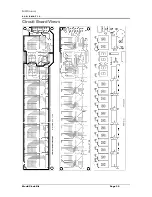
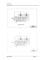
Page 32: ...KABtronics S C H E M A T I C World Clock Kit Page 32 Circuit Board Views...

Page 33: ...KABtronics S C H E M A T I C World Clock Kit Page 33 Top Side Copper Bottom Side Copper Silk Screen Schematic...

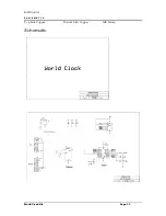
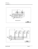
Page 34: ...KABtronics S C H E M A T I C World Clock Kit Page 34...

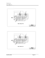
Page 35: ...KABtronics S C H E M A T I C World Clock Kit Page 35...

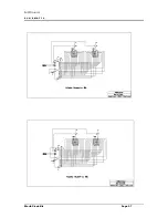
Page 36: ...KABtronics S C H E M A T I C World Clock Kit Page 36...

Page 37: ...KABtronics S C H E M A T I C World Clock Kit Page 37...

Reviews: