DC overvoltage protection
↻
NOTE: If "defective" appears in the status display of the overvoltage
protection module, it must be replaced.
↻
NOTE: Absence of AC/DC voltage ensured.
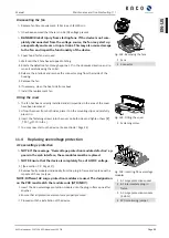
2. Unlock faulty modules via the locking latch.
3. Remove the defective modules one-by-one out of the DC base and replace with
a module of the same type.
.
NOTE: The coding at the base plug-in position must match the cod-
ing on the module.
4. Insert the DC overvoltage protection modules into the DC base one after an-
other.
5. Secure new modules using the locking latch.
6. Ensure that all protective elements are properly secured.
ð
Proceed with the installation of the device.
1
3
2
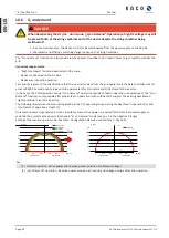
Fig. 105:
Inserting overvoltage
modules
1 DC base
2 DC overvoltage protection
module (3 slots)
3 Jumper
11.5
Shutting down for maintenance / troubleshooting
Shutdown sequence
1. Switch off the grid voltage by turning off the external circuit breakers.
2. Disconnect the DC side using the DC isolator switch.
.
DANGER! The DC cables are still live
ð
After shutdown, wait 5 minutes before opening the device.
11.6
Faults
11.6.1 Procedure
DANGER
Lethal voltages are still present in the connections and cables of the device even after the device
has been switched off and disconnected!
Severe injuries or death may occur if the cables and/or terminals/busbars in the device are touched.
1. If a fault occurs, notify an appropriately authorized and qualified electrician or KACO new energy GmbH
Service.
2. The operator can only carry out actions marked with a B.
11 | Maintenance and troubleshooting
Manual
KACO blueplanet 110 TL3 KACO blueplanet 125 TL3
Page 100
EN-US


