The transient response of the control methods is determined by a PT-1 filter. In this case, the settling time cor-
responds to 5 Tau, or in other words, achieving approx. 99% of the final value for a PT-1 filter. Subject to the
control method selected, there are also other parameters that determine dynamic behavior.
10.1.3 Reactive power functions
The following functions for controlling the reactive power are implemented in the devices listed above:
– cos ϕ constant
– Q constant
– cos ϕ /(p/pn)
– Q(U) 10 nodes
NOTE: Reactive power is prioritised in each method. The maximum possible active power that
can be fed in is reduced in line with the P-Q operating range when a specific reactive power
level is specified.
cos-φ constant
In
cos ϕ
-constant mode, the specified power factor is fixed by the inverter. In doing so, the reactive power
level is set in line with Q=P*tan ϕ as a function of the power that continuously generates the specified power
factor. If the set value is changed, the new value is taken over damped by a filter. The settling time can be pa-
rameterised and is 1s (this corresponds to 5 tau. (The VDE templates usually specify 3 Tau)) with the transient
response of a first-order filter (PT-1) with a time constant of Tau=200ms. The specified power factor can be
configured on the display or by way of communication via the KACO RS485 protocol and MODBUS/SunSpec.
If the applicable grid code stipulates that the cos-ϕ should react to the target value slower than the configured
Tau=200 ms by way of a defined gradient or settling time, this gradient or settling time must be implemented
in the system control.
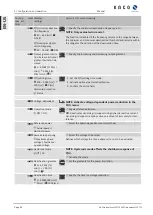
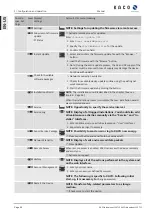
Parameter
Setting
Refer-
ence
Description
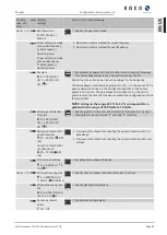
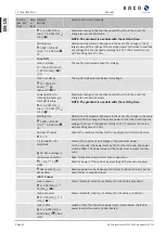
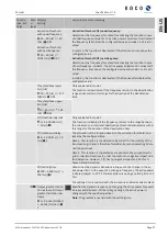
cos-phi const.
[OutPFSet]
1-0,3 [°]
Set the power factor to a certain % value.
Increasing power gradient
& Decreasing power gradi-
ent
[OutPFSet_RmpTms]
1 – 65524 [% Slim / min]
Specifies the dynamic behaviour when
changing the power factor cos ϕ. The
power factor is changed with the set gradi-
ent.
Note: The gradient is overlaid with the set-
tling time.
Settling time
[OutPFSet_WinTms]
1000 – 120000 [ms]
Set the settling time in the event of an
abrupt change in the reactive power target
value (e.g. caused by a voltage jump).
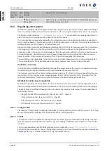
Timeout
[
OutPFSet_RvrtTms]
0 – 1000 [s]
Sets the time after which the inverter, if it
does not receive a new power factor speci-
fication, falls back to the previously valid re-
active power procedure.
If the
Timeout
is set to
0
seconds, the
transmitted power factor specification is
permanently retained, even in the event of
a communication failure.
Note: when the unit is restarted, the
Timeout
is reset to the set fallback time.
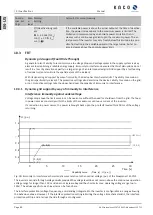
Q constant
In Q-constant mode, the specified reactive power value is permanently set by the inverter. If the constant is
changed, the new value is adopted by way of a filter in a muted manner. The settling time is 1s with the tran-
sient response of a first-order filter (PT-1) with a time constant of Tau=200ms. The specified reactive power can
be configured on the display or by way of communication via the KACO RS485 protocol and MODBUS/SunSpec.
Manual
Specifications | 10
KACO blueplanet 110 TL3 KACO blueplanet 125 TL3
Page 77
EN-US

