6.3
Fastening the mount
CAUTION
Hazard when using unsuitable fixing materials!
If unsuitable fixing materials are used, the device could fall and persons in front of the device may be seri-
ously injured.
›
Use only fixing materials that are suitable for the mounting base. The fastening materials supplied are
only suitable for masonry and concrete.
›
Only install the device in an upright position.
1
2
3
4
5
6
7
111 mm
A
A
C
B
D
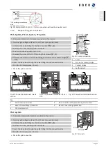
Fig. 12:
Minimum clearances for wall mounting
**
**
8
1
400 mm
250 mm
600 mm
1150 mm
Fig. 13:
Wall mounting
Key
1
Mount
5
Screw for securing purposes (1x)
2
Fixings for mounting [S12 – Ø 12mm/ 90mm]
6
Bracket to prevent device displacement
3
Lock washer
7
Marking as installation aid
4
Screws for mounting (5x) [SW 13 / Fastening the
mount [See section 6.3
8
Seating recess
A
Minimum clearance: 120 mm (without device370
mm )
recommended distance400 mm (without device 550
mm *)
C
Minimum clearance: 500 mm
B
Minimum clearance: 300 mm
D
Recommended clearance: 550 mm
↻
Cardboard packaging with mount and mounting kit removed from the packaging and opened.
1 Mark the mounting position on the wall surface according to the position of the mount by drawing a line.
2 Mark the positions of the drill holes using the slot in the mount.
NOTE: The minimum clearances between two devices, or the device and the ceiling or floor have already been
taken into account in the diagram.
3 Fix the mount to the wall using suitable mounting fixtures from the mounting kit.
NOTE: Make sure that the mount is oriented correctly.
»
Proceed with the installation of the device.
Kaco blueplanet 29.0TL3
Page 18
EN


