Installation Instructions Powador 1501xi/2501xi*/3501xi/4501xi/5001xi**_EN
Page 13
If the inverter is built into a switching cabinet or similar,
–
provide forced ventilation to ensure that heat is suffi ciently
dissipated
The heat sink may reach a max. temperature of 90 °C.
–
Therefore, mount the inverter only on walls made from heat-
resistant material
Ensure that the wall has adequate load-bearing capacity and
–
use appropriate installation material
Be sure to install the inverter in a suffi ciently elevated place,
–
especially in areas prone to fl ooding
Installation at eye level makes it easier to read the display.
–
6.2 Installing the inverter
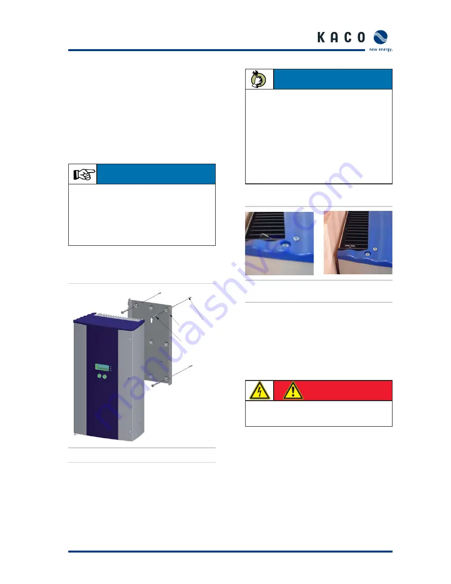
Dowel
Notches for mounting
the Powador
M5 screw
Figure 6.1:
Powador wall bracket
An installation kit consisting of four dowels and four 70 mm
Spax screws is supplied with the inverters. Check the composi-
tion and condition of the wall before installation. If necessary,
use an installation kit other than the one supplied with the
inverter.
Figure 6.2:
Safety catch
open (left) and closed (right)
6.3 Electrical connection
General information
After the inverter has been installed in its fi xed location, the
electrical connection to the unit can be established.
You must adhere to all mandatory safety regulations, the
currently required technical connection specifi cations of the
responsible power supply company, as well as to other gener-
ally applicable local regulations.
S e c t i o n 6 ·
I n s t a l l a t i o n a n d S t a r t - u p
IMPORTANT
Due to the high system voltage, it is possible that the
current that fl ows on the DC side may be lower than the
current that fl ows on the AC side. If the cable cross-sections
are the same, losses on the AC side lead are, therefore,
higher than those on the DC side. For this reason and due
to thermal factors, it makes sense to position the inverter
near the meter.
ACTION
Drill the holes for the dowels at the selected installation
–
position to match the cut-outs in the mounting plate.
Place the dowels into the holes.
–
Use the Spax screws to mount the wall bracket onto the
–
wall at the selected location. When doing so, ensure that
the arrow cut into the mounting plate points upwards.
Mount the inverter on the mounting fi xture so that the
–
pegs in the heat sink rest in the notches.
Lock the safety catch. To do this, slide the upper end of
–
the safety catch towards the wall until the groove runs
parallel to the wall (see fi gure 6.2).
DANGER
The Powador may only be installed by trained and
authorised specialists.


