Page 22
Operating Instructions Powador-proLOG_EN
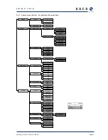
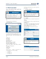
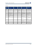
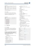
Description of the menu items:
Overview
You can see the current TCP/IP settings for your Ethernet con-
nection here. For GSM/GPRS units, you can also query the
fi eld strength.
▲
Ethernet
Current IP address: Shows the current IP
address that is used in the LAN.
• Current subnet mask: Shows the current
subnet mask that is used in the LAN.
• Current gateway: Shows the current gateway-
that is used in the LAN.
▲
GSM/GPRS
• Field strength: Indicates the fi eld strength.
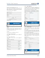
Settings
In the “Communication” section, you can make numerous
communication settings, e.g. change IP addresses or set the
PIN code for the GSM card. You can set the respective local
language in the second section, which is the “Language” sec-
tion. In the third section, which is the “Data logger” section,
you can trigger an inverter scan and activate the power con-
trol function. You can also reset the data logger to its factory
settings.
▲
Communication
• Ethernet
→
Boot protocol
none:
No boot protocol is used.
DHCP (Dynamic Host Confi guration Protocol):
A DHCP server assigns an IP address to the
Powador-proLOG.
BOOTP (bootstrap protocol):
The BOOTP server assigns an IP address to the
Powador-proLOG.
RARP (Reverse Address Resolution Protocol):
A RARP server assigns an IP address to the
Powador-proLOG.
→
Static IP address:
The IP address that is used when
no boot protocol was selected.
→
Subnet mask:
The subnet mask that is used when one was
not assigned by the BOOTP/DHCP server.
→
Gateway:
The gateway that is used when one was
not assigned by the BOOTP/DHCP server.
•
Modem/ISDN/GSM
→
Local IP address:
The IP address that the Powador-proLOG has in the
WAN.
→
Remote IP address:
The IP address that the caller must have on the WAN
.
→
Subnet mask:
The subnet mask in the WAN
→
MSN (ISDN only): MSN setting
→
PIN Code (GSM only): GSM pin setting
▲
Data logger
Inverter
settings
•
Start scan: Use this option to search for inverters.
•
Activate power control
•
Set factory settings
Reset to factory settings.
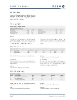
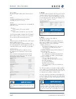
Current values
The current measured values are displayed here. Various que-
ries are possible, depending on which units are connected.
▲
Analogue values
Shows the analogue measured values.
▲
Digital values
Shows the digital measured values.
▲
Current sensors
Shows the measured values for the current sensors
▲
Inverters
Shows the current power of the individual
inverters.
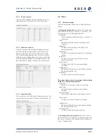
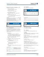
System
In the “Power/Energy” section, you can read the current
total power and the energy that is fed in during various time
periods. The “Alarms/Faults” section shows messages about
faults detected in the system.
▲
Energy of DI
If at least one digital channel was selected to calculate
the overall system power, the relevant measured
value will be displayed in the following submenus.
→
Current power
→
Yield today
→
Yield yesterday
→
Monthly yield
→
Annual yield
→
Total yield
▲
Energy Inverters
If the inverters were selected to calculate the total system
power and energy, the relevant measured value will be dis-
played in the following submenus.
→
Current power
→
Daily energy
→
Previous day's energy
→
Energy for the month
→
Annual energy
→
Total energy
S e c t i o n 6 ·
S t a r t - u p


