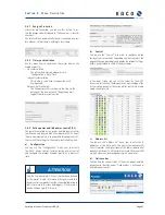
Operating Instructions Powador-proLOG_EN
Page 43
9.3.1 Basic principle of monitoring
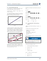
A relationship between irradiance and generated energy is
used for the physical basis. Ideally, this means that:
[generated power] = [irradiance * area of module * eta
module * eta inverter]
For PV modules with a degree of effi ciency of 12%, an inverter
degree of effi ciency of 91%, and a module area of 10 m², the
idealised relationship can be displayed as follows:
In reality, this relationship is not exactly linear across the entire
range (lower irradiance => lower degree of effi ciency). There-
fore, a solution must be found for a working fault message cri-
terion. For this purpose, a range is “stretched” so that meas-
ured values can move. This requires two linear equations that
defi ne the upper and lower limits of the “plausible” range:
In order to allow the maximum amount of fl exibility in select-
ing the range, two different slopes can be defi ned. The dis-
placement of the linear slopes by tHigh and tLow is specifi ed
as an absolute quantity (e.g. 0.2 kW).
0
0,1
0,2
0,3
0,4
0,5
0,6
0,7
0,8
0,9
1,0
1,1
Gmod [W/m²]
P
ac
[kW]
0
100
200
300
400
500
600
700
800
900
1000 1100
Pac = Gmod * eta mod * eta WR * area
-0,4
-0,2
0
0,2
0,4
0,6
0,8
1,0
1,2
1,4
Gmod [W/m²]
P
ac
[kW]
0
100
200
300
400
500
600
700
800
900 1000
6
5
4
3
2
1
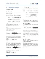
The equations for the linear slopes can now be written as fol-
lows:
Lower limit:
Upper limit:
where: mlow
= 0.85 tlow = - 0.25
mhigh
= 1.1 thigh = 0.15
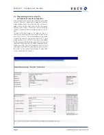
9.3.2 Setting parameters for the measuring
device
Settings are made in: Admin monitoring -> Formulas -> Cri-
terion x”)
First make the basic settings for this alarm criterion.
–
Designation: “Power by irradiance”
–
Status.“Active”
–
Time: “Interval”
–
Alarm destination: “Standard contact”
–
Message type: E-mail
–
Delay: “8”
(This sets a measuring interval of 15 minutes and an alarm
delay of two hours)
The formula entries are then as follows:
Y
Generation for photovoltaic system (dig_0)
m (lower
limit)
0.85
m (upper
limit)
1.1
x
Irradiance of module
(ana_0); System area; *eta PV;*eta inverter;*
c (lower
limit)
200
c (upper
limit)
200
S e c t i o n 9 ·
C o n f i g u r a t i o n E x a m p l e
Y
<
m
lower
X
t
lower
Pac
<
m
lower
(
G
Module
A
Arry
η
PV
η
INV
) (
t
lower
P
nom
)
Y
>
m
upper
X
t
upper
Pac
>
m
upper
(
G
Module
A
Arry
η
PV
η
INV
) (
t
upper
P
nom
)
ATTENTION
To send an alarm message, you have to specify the con-
tact for the alarm destination in“Admin monitoring ->
Contact addresses -> Contact x”).


