©2012 Kaelus, Inc. All rights reserved
.
ACU0001F1V1-1 User Guide
3
1.2 ACU Hardware
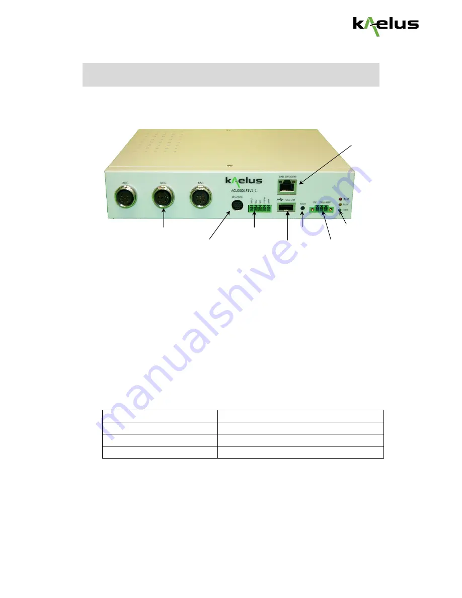
The following figure shows the front view of the ACU controller.
The front panel of the ACU controller has the following connectors:
3 x AISG female ports used to connect to AISG line devices.
Power port used to connect to the power source.
RS-232 port used to connect to the serial port of a PC for console access.
Reset button. Press to restart the ACU controller.
Alarm LED indicator. Lights up or blinks when there is an alarm.
Run LED Indicator. Blinks when the system is running.
Power LED indicator. Lights up when the power is connected.
Ethernet port used to connect to a PC or a network.
USB port used to connect to an USB device.
Relay alarm port
Alarm Connector Label
Relay's Switch Connections
O1
Normal Closed Contact (NC)
O2
Normal Open Contact (NO)
O3
Common (COM)
Max. Allowable Voltage: 265VAC / 30VDC
Max. Allowable Current: 10A
Max. Allowable Power: 1200VA / 280W
Ethernet port
Alarm / Run / Power
Reset
Relay Alarm port
3x AISG female ports
RS-232 port
USB port
Power port


