background image

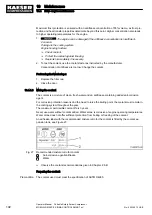
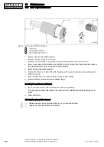
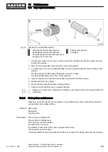
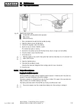
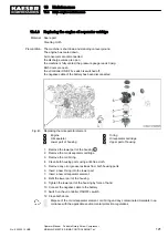
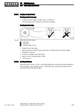
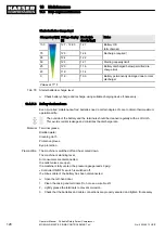
5. Remove the dipstick once more and read off the oil level.

The oil level is between the upper and the lower mark: The oil level is in the correct range.
The level has reached the lower mark 

minimum level or is below the mark: Replenish engine

oil.

6. Close the door.

The marked 

maximum oil level should not be exceeded in order for the level of oil in the

crankcase not to reach the crankshaft. If this were to occur, it could create oil bubbles that

would reduce the oil's lubricating capability and impair engine performance.

10.4.5  Engine oil filling and topping off

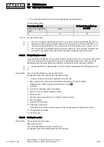
Material New engine oil, see chapter 2.8.5 for drive engine filling quantity.

Cleaning cloth
Funnel

Precondition The machine is switched off.

The machine is standing level.
Air consumers are disconnected,

the outlet valves are open,

the machine is fully vented, the pressure gauge reads 0 psig.
«Controller ON/OFF» switch is switched off, the minus cable of the battery has been disconnected.

Filling with engine oil

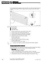
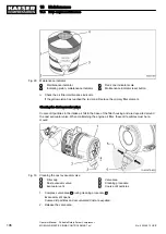
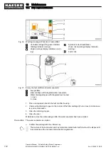
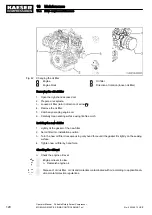
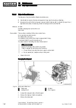
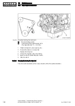
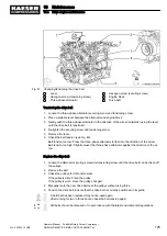
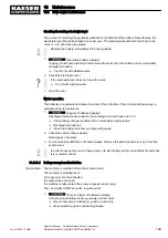
Pay attention to the «maximum oil level» mark on the oil dipstick.

1. Open the left-hand door.
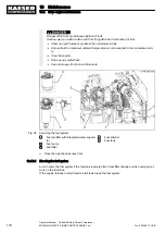
2. Loosen and remove the oil filler cover.
3. Fill with fresh engine oil.

It takes a few minutes for oil to reach the sump.

4. Wait for at least 5 minutes.
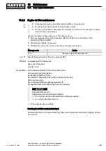
5. Check the oil level.

Low oil level: Replenish engine oil.

6. Replace the plug in the filler port.

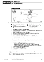
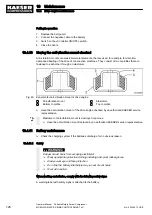
Preparing for operation

1. Connect the negative battery terminal.
2. Switch on the «Controller ON/OFF» switch.
3. Close the door.

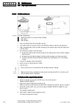
Starting the machine and performing a test run

1. Switch on machine by using the «START» key on the control panel of

SIGMA CONTROL SMART.

2. Warm-up machine by letting it run in IDLE mode.

10 Maintenance

10.4 Drive engine maintenance

116

Operator Manual    Portable Rotary Screw Compressor  
MOBILAIR M55 PE  SIGMA CONTROL SMART pV

No.: 902366 10 USE

Summary of Contents for MOBILAIR M55 PE

Page 1: ...l Portable Rotary Screw Compressor MOBILAIR M55 PE SIGMA CONTROL SMART pV No 902366 10 USE Manufacturer KAESER KOMPRESSOREN SE 96410 Coburg PO Box 2143 GERMANY Tel 49 0 9561 6400 Fax 49 0 9561 640130...
Page 2: ...Original instructions KKW M55PE 2 09 en Z1 SBA MOBILAIR 20220325 111411...

Page 3: ...ht of machines with stationary frame design 8 2 7 Compressor 9 2 7 1 Variable pressure flow rate control pV control 9 2 7 2 Compressed air outlet 12 2 7 3 Safety relief valves 12 2 7 4 Temperature 12...

Page 4: ...re flow rate control pV control 44 4 8 Exhaust gas after treatment 44 4 8 1 Engine optimization 44 4 8 2 Exhaust gas treatment system 45 4 8 3 Regeneration of the diesel particulate filter 46 4 9 Opti...

Page 5: ...nterior of the machine 78 8 6 Operating the options 79 8 6 1 Bypassing switching on the heat exchanger 79 9 Fault Recognition and Rectification 9 1 Basic instructions 82 9 2 Analysing SIGMA CONTROL SM...

Page 6: ...ues 155 10 8 3 Sealed screw connections 155 10 9 Check wing doors 155 10 9 1 Maintain rubber sealing strips 156 10 9 2 Checking function of closed enclosure 156 10 9 3 Checking connecting elements of...

Page 7: ...machine 243 13 1 2 Identification of the drive engine 243 13 1 3 Identification of the exhaust gas after treatment system 244 13 2 Pipeline and instrument flow diagram P I diagram 244 13 3 Dimensiona...

Page 8: ...Contents vi Operator Manual Portable Rotary Screw Compressor MOBILAIR M55 PE SIGMA CONTROL SMART pV No 902366 10 USE...

Page 9: ...the coolant level 101 Fig 27 Recommended mixture ratio for coolant 102 Fig 28 Draining the coolant 104 Fig 29 Maintenance indicator 106 Fig 30 Cleaning the dust evacuator valve 106 Fig 31 Engine air f...

Page 10: ...portation by crane 230 Fig 70 Prohibition signs for forklift transport 232 Fig 71 Forklift example Lifting accessory components 232 Fig 72 Ensure both fork prongs are positioned under the machine 233...

Page 11: ...14 Tab 30 Engine oil recommendation 15 Tab 31 Viscosity class for first fill 15 Tab 32 Water quality specification 16 Tab 33 Initial fill of coolant cooler 17 Tab 34 Fluid volumes 17 Tab 35 Batteries...

Page 12: ...options 99 Tab 74 Coolant mixture table 103 Tab 75 Specific message code for Service engine air filter 105 Tab 76 Specific message code for Change the engine oil 117 Tab 77 Specific message code for C...

Page 13: ...SER Make sure all documents are complete and observe the instructions contained in them Make sure you provide the data from the nameplate when ordering documents 1 3 Copyright This operator manual is...

Page 14: ...a warning are shown here The word WARNING indicates that death or severe injury may result from ignoring the warn ing The measures required to protect yourself from danger are shown here 2 Always read...

Page 15: ...n of the previous action Information relating to one option only is marked with an option code e g option da means that this section is only valid for machines with the air treatment components afterc...

Page 16: ...ication feature on the machine The vehicle identification number remains associated with the machine throughout the entire dura tion of its service life The vehicle identification number is stamped in...

Page 17: ...ons as reference in the below overviews 2 3 1 Option da df dd Air treatment Option Option code Equipped Compressed air aftercooler and water separator da Heat exchanger with bypass df Filter combinati...

Page 18: ...code Available GSM GPS modem oc Tab 8 GSM GPS modem 2 3 6 Option ta tb tc te Lighting Option Option code Available None stationary ta Reflective warning triangle tb EG 12 V tc USA 12 V DOT conformity...

Page 19: ...e as appropriate for the surface finish and friction coefficient Standard values for M4 M8 screws with steel grade 8 8 Thread M4 M5 M6 M8 Torque lbf in 26 6 52 2 88 5 216 8 Surface finish zinc plated...

Page 20: ...ensions track width footprint can be found in the dimensioned drawings in Chapter 13 3 The dimensional drawings also show the position of the following inlets and outlets Cooling air inlet Cooling air...

Page 21: ...sure Nominal system pressure and flow rate Nominal system pressure and engine speed 2 7 1 1 Maximum machine working pressure Maximum working pressure psig 125 150 SIGMA airend 17 G 17 G Setting range...

Page 22: ...cation example a1 95 190 Hammer application Blasting application a2 100 185 Cable injection a3 125 155 Hammer application Blasting application Tab 18 Flow rate depending on the nominal system pressure...

Page 23: ...tic line nominal system pres sure 90 150 n Engine speed rpm p Nominal pressure psig Setting range nominal system pressure 90 125 psig engine speed Measuring point Pressure stage nominal pressure psig...

Page 24: ...temperatures readiness to switch to LOAD mode Values Airend discharge temperature ADT F 68 Engine coolant temperature ECT F 68 Tab 24 Required temperatures readiness to switch to LOAD mode Airend dis...

Page 25: ...STM test 53 7 lb ft3 D 4052 ASTM test 54 2 lb ft3 D 4052 ASTM test Pour point 22 F D 97 ASTM test 16 6 F D 97 ASTM test 65 F D 97 ASTM test Tab 26 Cooling oil recommendation Cooling oils for applicati...

Page 26: ...700 Speed at IDLE operation rpm Approx 2100 Type of fuel Diesel Fuel consumption under LOAD operation gal h 2 7 Oil consumption relative to fuel consumption Approx 0 5 Tab 29 Engine specification 2 8...

Page 27: ...tem must be operated only with a sulphur free diesel fuel Compliance with the emission requirements but also the durability of the individual exhaust gas treatment components is not assured if this re...

Page 28: ...er quality specification Contact the local water utilities for information regarding water quality If the water does not meet the above parameters it must be treated If suitable water is not available...

Page 29: ...rs antifreezes is not recommended even if from the same manufacturer This can result in significantly reduced corrosion antifreeze protection which may damage the engine cooling system and consequentl...

Page 30: ...G Tab 36 Interrelation between compressed air treatment and compressed air quality The compressed air outlets at the air distributor are labelled with the identifiers of com pressed air quality 2 9 2...

Page 31: ...d in this service manual Operate the machine only within its performance limits and under the permitted ambient condi tions Do not use compressed air for breathing purposes unless it is specifically t...

Page 32: ...They must be of legal age They must have read and understood the safety instructions and sections of the operating manual applicable to cleaning and they must be capable of observing them They must b...

Page 33: ...or the last inspection Contact an authorized KAESER serv ice representative Tab 39 Inspection intervals according to Ordinance on Industrial Health and Safety Checking the lifting point The user is r...

Page 34: ...carrying components can result in electric shocks burns or even death Allow only qualified and authorized electricians or trained personnel under the supervision of a qualified and authorized electri...

Page 35: ...n place and secured before re starting Temperature The operation of the combustion engine and the compression generate high temperatures Touch ing hot components may cause injuries Avoid contact with...

Page 36: ...in unpredictable hazards Do not convert or modify the machine Do not install any non approved additional components Do not make any changes to the machine that will increase its weight beyond the per...

Page 37: ...ning gear including chassis wheels brakes signalling and lighting is in safe condition The local laws and regulations regarding the use of public roads must be observed Transporting with a crane Non c...

Page 38: ...ition the machine in the warm exhaust air flow from other machines Keep suitable fire extinguishing agents ready for use Chock the wheels to prevent unwanted movement Do not place additional loads on...

Page 39: ...y a safety cable to their respective outlet valves 3 5 2 4 Parking the machine Improper parking and use of the parked machine endangers personnel and material Select an even surface for parking Use a...

Page 40: ...machine Within a 3 ft radius of the machine Maintenance personnel Tab 40 Danger areas 3 6 Safety devices Safety devices ensure safe working with the machine Do not change bypass or disable safety devi...

Page 41: ...n this machine 310 311 Injury or damage from open machine Operate the machine only when closed Transport the machine only when closed 330 331 333 Hot surface can cause burns Let the machine cool down...

Page 42: ...nd FDA 21 CFR178 3570 standards if used for breathing or food process ing Use proper compressed air treatment Food grade coolant must be used for food processing 450 Loud noise and compressed air blas...

Page 43: ...battery fluid is frozen Bring temperature of battery up to at least 60 F before attempting to jump start it may explode 303 Fire or explosion caused by refueling Severe injury or death result from inf...

Page 44: ...irements Tampering with the noise control system is prohibited Federal law prohibits the following acts or causing thereof The removal or rendering inoperative by any persons other than for purposes o...

Page 45: ...ctrolyte tool lubricant option e Eye contact Fuel oil and other fluids materials can cause irritation Rinse eyes thoroughly with lukewarm water and seek medical assistance immediately Skin contact Fue...

Page 46: ...able American EPA noise control regulations This warranty is not limited to any particular part component or system of the air compressor Defects in the design assembly or in any part component or sys...

Page 47: ...pplies particularly to parts contaminated with fuel oil coolants reduction agents and acids For the emission output of the corresponding engine class to always comply with applicable requirements the...

Page 48: ...several functions when it is closed Weather protection Sound insulation Protection against touching Cooling air flow The bodywork is not suitable for the following uses Persons walking standing or si...

Page 49: ...he wing doors are provided with handles for opening Release the doors by the snap fasteners The doors are held open by gas springs 4 Design and Function 4 1 Bodywork No 902366 10 USE Operator Manual P...

Page 50: ...st gas after treatment with diesel oxidation catalyst and diesel particulate fil ter 9 Coolant cooler 10 Oil cooler 11 Exhaust gas pipe 12 Drive engine 13 Airend 14 Oil separator tank 15 Oil filter 16...

Page 51: ...options Item numbers correspond to the pipe and instrument flow diagram P ID in chapter 13 2 4 Design and Function 4 3 Machine function No 902366 10 USE Operator Manual Portable Rotary Screw Compress...
Page 52: ...alve oil temperature con trol 20 Oil cooler 21 Oil filter 24 Engine air filter 28 Fan wheel 29 Exhaust gas after treatment with diesel oxi dation catalyst and diesel particulate filter 37 Minimum pres...

Page 53: ...ssure to ensure continuous cooling oil flow in the machine The flow direction of the fan wheel 28 and arrangement of the cooling air inlet and outlet deter mine the cooling air flow of the machine wit...

Page 54: ...rs This continuous delivery regulation minimizes the fuel consumption of the engine The load and fuel consumption of the engine rises and falls with the air demand 4 5 Safety devices 4 5 1 Monitoring...

Page 55: ...edges resets mainte nance tasks Returns to the superordinate menu item press quickly Closes the menu press for at least two seconds 4 Key LOAD IDLE Toggles the compressor between LOAD and IDLE operati...

Page 56: ...State of the art engine technologies are used to reduce the emission of pollutants and to meet the tighter exhaust standards For a proper balance all parameters affecting combustion must be optimally...

Page 57: ...side of the en gine where it is added to the inlet air This reduces the available oxygen volume and thus the com bustion temperature Both measures reduce the development of nitrogen oxides Exhaust ga...

Page 58: ...es present in the diesel engine ex haust fine solids and mostly soot Nearly all of these particles are trapped in the filter and burnt to CO2 at high exhaust gas temperature At a low exhaust gas tempe...

Page 59: ...iesel particu late filter remains in a permissible range Parked regeneration activated by operator If the passive regeneration does not result in a sufficient reduction of the soot load the particulat...

Page 60: ...is collected in the water separator 4 9 1 3 Option da Dirt trap with condensate drain line A dirt trap is located beneath the water separator While the condensate flows through the dirt trap existing...

Page 61: ...is equipped with a GSM GPS modem This modem can be equipped with a SIM card and serves for connection to the MOBILAIR fleet management system The GSM GPS modem has only indicating functions Fig 12 Lo...

Page 62: ...red with a retaining clip To unlock the cover press the retaining clip in the direction of the arrow 5 4 9 4 Transport options See the separate document Chassis Operating Manual for information on the...

Page 63: ...e Mounted on truck trailer platform Tab 45 Stationary machines Further information See chapter 13 3 for the dimensional drawings of machines with stationary frame designs 4 Design and Function 4 9 Opt...

Page 64: ...requirements with regard to explosion protection are in force For instance the requirements of ATEX directive 2014 34 EC Equipment and Protective Sys tems intended for use in Potentially Explosive Atm...

Page 65: ...the machine 5 Ensure there is enough free space all round and above the machine 6 Keep air inlet and outlet openings free of obstructions so that the cooling air can flow freely through the machine 7...

Page 66: ...re that an emergency shut down is possible 3 Ensure sufficient clearance for air supply to and exhaust lines from the machine while fastened to the platform Keep the intake air openings unobstructed K...

Page 67: ...the machine for visible and hidden transport damage 2 Inform the carrier and the manufacturer in writing of any damage found 6 3 Perform regular maintenance on the chassis See the separate document C...

Page 68: ...on Fig 15 Mounting machine foot rubber pad 1 Machine 2 Machine s support frame support 3 Machine foot anti vibration metal ele ment 4 Hexagon bolt 5 Washer 6 Rubber pad 1 Position the bolt down machin...

Page 69: ...2 Details of dangers and their avoidance are found in chapter 3 5 7 2 Before initial start up or recommissioning Incorrect or improper commissioning can cause injury to persons and damage to the mach...

Page 70: ...d air control air condensate for leaks loose connections wear and damage Body Clean the body with a grease and dirt dissolving agent 36 months Technical condition Have the overall technical condition...

Page 71: ...start up of the machine is performed via an automa ted start up process When the START key on the control panel of the SIGMA CONTROL SMART is pressed the en gine begins a maximum of three automatic s...

Page 72: ...art up cycles successfully starts up the machine 7 4 1 3 Actions required following a successful start up 1 Run the machine load free with the compressed air discharge valves open until it has warmed...

Page 73: ...Allow the battery to thaw first Do not try to start the machine with a boost charger 2 Comply with the safety instruction shown when using starting aids and starter batteries Preparations 1 Park the...

Page 74: ...e The engine electronics of the machine in particular is sensitive to high voltages and could be da maged easily Disconnecting the battery jumper cables 1 Stop the engine of the assisting vehicle 2 Di...

Page 75: ...shocks burns or death Work on electrical equipment may only be carried out by authorized electricians Safe working with compressed air tools and hoses Open pressurized compressed air hoses move errati...

Page 76: ...carried out in the sequence given here Starting instrument layout on control panel Keys and indicators on the SIGMA CONTROL SMART control unit Controller ON OFF switch Quick reference guide Start up p...

Page 77: ...MA CONTROL SMART control unit 9 Up and Down keys 10 Enter key 11 LOAD IDLE key 12 OFF key 13 START key 14 Status bar a Control voltage ON b READY flashing 15 Menu bar c Settings menu 16 Navigation men...

Page 78: ...erence guide displayed as symbols for the start up and shutdown procedures can be found on a label on the control panel cover Memorize the symbols for the start up and shutdown procedures Start up sym...

Page 79: ...the machine if the EMERGENCY STOP push button does not func tion Permissible total weight of the machine exceeded Remove snow and or ice from the machine Checking the EMERGENCY STOP push button 1 Act...

Page 80: ...s activated for 20 seconds The display shows the remaining time before anoth er start can be attempted Switching the machine to LOAD operation Press LOAD IDLE key The machine switches to LOAD mode and...

Page 81: ...the access type Quick access from the main menu Fig 22 Quick access adjustment compressed air output pressure 1 Symbolic setting the compressed air discharge pressure 2 Setting value 1 Press UP or DOW...

Page 82: ...a black background or 1 Press UP or DOWN until all lines of the Settings menu no longer have a frame 2 Press Enter for just a moment Jump back to the menu bar the Settings menu symbol receives a blac...

Page 83: ...hen the machine is fully vented the display changes to Ready to start When the OST is fully vented after shut down the re start inhibitor is activated and is in dicated by the timer counting down from...

Page 84: ...key 3 Restart the SIGMA CONTROL SMART to acknowledge the alarm message Result The machine is ready to start 8 3 Refueling the machine In order to avoid accidents caused by igniting fuel special cauti...

Page 85: ...e fuel system to be cleaned Arrange for the injection system to be checked replaced Arrange for the engine to be checked replaced Fill the tank with diesel fuel Tab 48 Measures required should the fue...

Page 86: ...information For more details on the correct fuel specification see Chapter 2 8 3 8 3 2 Filling the fuel tank at a pump by means of a refuelling nozzle Liquid fuels expand at high ambient temperatures...

Page 87: ...ne is standing level The machine has cooled down The enclosure is open All compressed air consumers are disconnected the discharge valves are open the machine is fully vented the pressure gauge reads...

Page 88: ...d the message still needs to be acknowledged by restarting the SIGMA CONTROL SMART Restart the SIGMA CONTROL SMART to acknowledge the alarm message The message is acknowledged The machine can be start...

Page 89: ...ollowing minimum distances to the object to be cleaned Circular section jet nozzles approximately 28 inches Fan jet nozzles approximately 12 inches Dirt blasters approximately 12 inches Cleaning by us...

Page 90: ...rect water or steam jets Cleaning the machine from the outside Maintain the following minimum distances to the object to be cleaned in order to prevent damages to the object when cleaning with the hig...

Page 91: ...l protection regulations 8 6 Operating the options Comply with all instructions 8 6 1 Option da df da dd df Bypassing switching on the heat exchanger A heat exchanger serves to reheat the treated comp...

Page 92: ...nd warm compressed air B 0 Condensate free compressed air A I directional control valve open 0 directional control valve closed Tab 50 Directional control valve position and selected compressed air qu...

Page 93: ...ional control valve open 0 directional control valve closed Tab 51 Directional control valve position and selected compressed air quality Switching on the heat exchanger 1 Always wear protective glove...

Page 94: ...er factory settings and individu al equipment with which the machine is provided 9 2 1 Fault messages on the controller machine off Fault with automatic shutdown of the machine Following rectification...

Page 95: ...rrange for it to be checked X X 1151 Fault ECU SCS com munication Arrange for it to be checked X X 1160 Fault rail pressure sen sor Arrange for it to be checked X X 1161 Fault speed sensor Arrange for...

Page 96: ...ked X SW Specialist Workshop KS KAESER SERVICE ADT Airend discharge temperature OST Oil separator tank Tab 53 Fault messages and actions relating to compressor fault Alarm codes range 1300 1399 Contro...

Page 97: ...lt inlet valve pres sure transducer open cir cuit Arrange for it to be checked repaired X 1414 Fault ADT sensor open circuit Arrange for it to be checked X 1416 Fault fuel level sensor open circuit Ar...

Page 98: ...water level Empty the fuel filter water trap 10 4 3 3150 Warning ECU miscella neous error Have it checked 3154 Warning drive motor engine sensor fault Have it checked X X 3155 Warning drive motor eng...

Page 99: ...Allow the machine to cool down 5 2 3313 Warning HMI tempera ture high Check operating condi tions Allow the machine to cool down 5 2 SW Specialized workshop KS KAESER SERVICE PLC Programmable logic c...

Page 100: ...e it checked X Oil pressure switch indicating in sufficient oil pressure Check the engine oil level see chapter 10 4 4 Have the engine repaired or ex changed X SW Specialized workshop KS KAESER SERVIC...

Page 101: ...r replaced if necessary X Inlet valve not opening or only opening partially Repair or have it replaced if necessary X Pressure gauge indicating incor rect reading Have it repaired or replaced if neces...

Page 102: ...ave it repaired or replaced if necessary X Working pressure too high pro portional controller maladjus ted Reset to the permissible value or have it replaced X Oil separator cartridge heavily clogged...

Page 103: ...ossible cause Remedy Where can I get help SW KS Defective non return function of the inlet valve Repair or have it replaced if necessary X SW Specialized workshop KS KAESER SERVICE Tab 66 Alarm Oil fl...

Page 104: ...Tab 68 Advise others that the machine is being serviced Before switching on make sure that nobody is working on the machine all protective guards and cover panels are attached all doors and panels are...

Page 105: ...ller display 10 2 1 Evaluating maintenance messages Determine any upcoming maintenance tasks using the table below and perform the mainte nance in accordance with the maintenance schedule provided in...

Page 106: ...timer Precondition Maintenance has been completed and the maintenance message acknowledged Reset the maintenance timer as described in the separate user manual for SIGMA CONTROL SMART chapter Reset m...

Page 107: ...tenance tasks after commissioning The table below lists maintenance tasks required after commissioning initial start up 10 3 2 1 Maintenance tasks on the machine after commissioning Carry out maintena...

Page 108: ...nce activities marked with 2 in accordance with country specific regu lations Change the oil as per requirement once per year at a minimum Observe the maintenance tasks marked with 3 in accordance wit...

Page 109: ...nk strainer X Have the injection valve tip checked X KS SW Check and maintain the battery X 10 4 11 Have the antivibration mount checked X 10 4 10 KS SW Exhaust gas after treatment Check the exhaust s...

Page 110: ...ssor air filter X 10 6 7 2 Change cooling oil X 10 6 3 Replace compressor oil filter X 10 6 4 Replace oil separator cartridge X 10 6 6 Safety functions Check EMERGENCY STOP push button X 10 11 1 Have...

Page 111: ...Workshop DPF Diesel Particulate Filter Tab 72 Regular machine maintenance tasks 10 3 3 2 Options maintenance schedule Carry out maintenance tasks according to the following schedule Option Task Daily...

Page 112: ...urns from coolants containing antifreeze Avoid eye and skin contact with coolant In case of contact rinse immediately with run ning water Wear protective glasses and protective gloves Insufficient coo...

Page 113: ...e Coolant quality can be determined by the following parameters Visual check Measuring the concentration of the antifreeze Loosen and remove the filler cap 5 Performing a visual check The coolant shou...

Page 114: ...and an antifreeze containing added anti corrosion agent For corrosion protection reasons and the need to raise the boiling point the coolant must remain in the cooling system throughout the year The...

Page 115: ...nd is therefore prohibited Ensure that there is sufficient space for the coolant to expand without overflowing when hot Precondition The Controller ON OFF switch is switched off the negative cable of...

Page 116: ...hose coupling The hose coupling is closed 7 Fit the protective cap onto the hose coupling Dispose of used coolant in accordance with environmental protection regulations Removing scaling from inside...

Page 117: ...sed air for blowing out Spare part if required Cleaning cloth Precondition The machine is switched off and has cooled down Air consumers are disconnected the discharge valves are open the machine is f...

Page 118: ...sing and are deposited around the dust evacuator valve When maintaining the engine air filter these dirt particles must be re moved Fig 30 Cleaning the dust evacuator valve 1 Filter cap 2 Dust evacuat...

Page 119: ...lter elements The engine air filter is fitted with two filter elements Primary filter element Secondary filter element The secondary filter element must be replaced at every third change of the primar...

Page 120: ...r housing with the dust evacuator valve pointing verti cally downwards 7 Place the filter cap on the filter housing and press down lightly 8 Secure the filter cap with all three retaining clamps Reset...

Page 121: ...ition the filter cap in place 6 Secure the filter cap with all three retaining clamps 7 Check to ensure the filter cap is correctly attached Dispose of old parts and contaminated materials in accordan...

Page 122: ...34 Servicing the fuel system 1 Fuel prefilter with integrated water separa tor 2 Fuel pump 3 Fuel filter 4 Fuel strainer 5 Fuel tank Open the right hand access door 10 4 3 1 Bleeding the fuel system...

Page 123: ...9 Check the fuel prefilter for leaks If any fuel has escaped Retighten filter cartridge and all screw connections 10 Close the door 10 4 3 2 Fuel pre filter maintenance Emptying the fuel water separat...

Page 124: ...le beneath the fuel pre filter housing 2 Unscrew the draining stopper on the bottom of the filter cartridge 2 turns max and drain wa ter and contamination 3 Close the draining stopper 4 Close the door...

Page 125: ...topper Seal damaged replace seal 8 Mount the draining stopper to a new filter cartridge 9 Clean the sealing faces of the filter cartridge and opposite side of the filter head with a lint free cloth 10...

Page 126: ...urn approxi mately 5 Connect the negative cable to the battery 6 Switch on the Controller ON OFF switch 7 Close the door The fuel system must be bled after the filter cartridge has been changed Dispos...

Page 127: ...n The machine is standing level Air consumers are disconnected the outlet valves are open the machine is fully vented the pressure gauge reads 0 psig Controller ON OFF switch is switched off the minus...

Page 128: ...are open the machine is fully vented the pressure gauge reads 0 psig Controller ON OFF switch is switched off the minus cable of the battery has been disconnected Filling with engine oil Pay attention...

Page 129: ...ecific message code for Change the engine oil Material Fresh engine oil Receptacle Male hose coupling separately enclosed with machine Cleaning cloth Precondition The machine is switched off The engin...

Page 130: ...old oil and oil soaked working materials according to environmental protection regulations Close the hose coupling of the engine 1 Loosen and remove the male hose coupling The hose coupling is closed...

Page 131: ...Precondition The machine is switched off the engine has cooled down Air consumers are disconnected the outlet valves are open the machine is fully vented the pressure gauge reads 0 psig Controller ON...

Page 132: ...e gasket of the new filter 2 Set oil filter into installation position 3 Turn the new oil filter clockwise using only hand force until the gasket fits tightly on the sealing surface 4 Tighten new oil...

Page 133: ...r part of the housing 3 2 Remove the old oil separator cartridge 3 Remove the old O ring 4 Clean both housing parts using a lint free cloth 5 Remove any oil or grease residues from both housing parts...

Page 134: ...achine is fully vented the pressure gauge reads 0 psig Controller ON OFF switch is switched off the minus cable of the battery has been disconnected Beware of rotating pulleys and moving belts There i...

Page 135: ...Replace the drive belt immediately 1 Replace the belt guard 2 Connect the negative cable to the battery 3 Switch on the Controller ON OFF switch 4 Close the doors 10 4 9 2 Checking belt tension Check...

Page 136: ...e belt 3 Replace the belt guard 4 Connect the negative cable to the battery 5 Switch on the Controller ON OFF switch 6 Close the doors 10 4 9 3 Changing tensioning the drive belt The drive belt is ten...

Page 137: ...gh Slightly swivel the three phase alternator against the direction of the ar row Replace the drive belt 1 Loosen the alternator securing screw and tensioning screw until the drive belt can be taken o...

Page 138: ...authorized KAESER service representative Elastomer of anti vibration mount is destroyed or porous Have the anti vibration mount replaced by an authorized KAESER service representative 10 4 11 Battery...

Page 139: ...ry to short circuit overheat or explode Take particular care when the battery has been in service for a long time or has just been charged as highly explosive gas is emitted Ensure adequate ventilatio...

Page 140: ...should be cleaned regularly with a soft cloth This avoids current leakage and minimizes the discharge rate Material Terminal grease Distilled water Cleaning cloth Protective gloves Eye protection Pre...

Page 141: ...t 14 F Check battery charge condition with an electrolyte density tester Recharge the batteries Clean the battery terminals and wipe with grease 2 Check the battery charge weekly Recharge as necessary...

Page 142: ...rent strength and form as the original bat teries Always replace batteries with the same type Old batteries are hazardous waste and must be disposed of correctly in accordance with local environmental...

Page 143: ...ield exhaust gas after treatment 1 Exhaust gas after treatment 2 Heat shield diesel particulate filter ex haust manifold 3 Heat shield exhaust gas pipe 4 Heat shield diesel particulate filter If neces...

Page 144: ...g the fixing elements Check all stepped band clamps are tightly fitted tighten if necessary Checking the exhaust manifold insulation Check the exhaust manifold insulation is tightly fitted and free fr...

Page 145: ...open the machine is fully vented the pressure gauge reads 0 psig The left hand door is open the Controller ON OFF switch is switched off the negative cable for the battery has been disconnected Fig 5...

Page 146: ...s open Controller ON OFF switch is switched off the minus cable of the battery has been disconnected Filling in cooling oil A sticker on the oil separator tank specifies the type of oil used 1 The mac...

Page 147: ...Top off the cooling oil 8 Visually inspect for leaks 9 Close the door 10 6 3 Changing the cooling oil All of the oil must always drain fully from the following components Airend Oil separator tank Oil...

Page 148: ...cooling oil Wear long sleeved clothing and gloves Open the left hand door 10 6 3 1 Draining the cooling oil In order to drain all of the cooling oil from the machine in a user friendly manner it is ne...

Page 149: ...ng in the floor panel 3 Suspend and fasten the free end of the male hose coupling inside the receptacle 4 Loosen and remove the protective cap from the hose coupling 5 Attach the male hose coupling to...

Page 150: ...upling on the oil separator tank 1 Loosen and remove the male hose coupling The hose coupling is closed 2 Return the protective cap to the hose coupling Closing the hose coupling on the oil cooler 1 L...

Page 151: ...Replace the plug in the filler port 4 Close the door 5 Prepare machine for operation 6 Start the machine and run it in IDLE speed for a short time 7 Switch off the machine 8 Wait until the machine ha...

Page 152: ...fic message code for Change the oil filter Material Long sleeved protective clothing Protective gloves Eye protection protective glasses Spare part Receptacle Cleaning cloth Precondition The machine i...

Page 153: ...oil filter into installation position 3 Turn the new oil filter clockwise using only hand force until the gasket fits tightly on the sealing surface 4 Tighten new oil filter by hand force Check the c...

Page 154: ...ccording to envi ronment protection regulations Resetting maintenance timer Reset the maintenance timer as described in the separate User Manual of SIGMA CONTROL SMART chapter Reset maintenance timer...

Page 155: ...ck the strainer and O ring for wear When severely worn replace components 5 Place the screw plug on the strainer 6 Install the screw plug making sure the O ring sits in the correct position 7 Tighten...

Page 156: ...OFF switch 3 Close the door 10 6 5 4 Starting the machine and performing a test run 1 Switch on machine by using the START key on the control panel of SIGMA CONTROL SMART 2 Warm up machine by letting...

Page 157: ...econdition The machine is switched off The machine has cooled down Air consumers are disconnected the outlet valves are open the machine is fully vented the pressure gauge reads 0 psig Controller ON O...

Page 158: ...tery terminal 2 Switch on the Controller ON OFF switch 3 Close the left hand door Dispose of old parts and contaminated materials according to environmental regulations Starting the machine and perfor...

Page 159: ...aterial Compressed air for blowing out Spare part if required Cleaning cloth Precondition The machine is switched off and has cooled down Air consumers are disconnected the discharge valves are open t...

Page 160: ...and are deposited around the dust evacuator valve When maintaining the compressor air filter these dirt particles must be removed Fig 60 Cleaning the dust evacuator valve 1 Filter cap 2 Dust evacuator...

Page 161: ...ter elements The compressor air filter is fitted with two filter elements Primary filter element Secondary filter element The secondary filter element must be replaced at every third change of the pri...

Page 162: ...housing with the dust evacuator valve pointing verti cally downwards 7 Place the filter cap on the filter housing and press down lightly 8 Secure the filter cap with all three retaining clamps Resett...

Page 163: ...lter element into the filter housing 5 Position the filter cap in place 6 Secure the filter cap with all three retaining clamps 7 Check to ensure the filter cap is correctly attached Dispose of old pa...

Page 164: ...mage or destroy electrical components and indicator gauges Cover up electrical components such as the control box alternator starter or indicating instruments Do not direct water or steam jets at sens...

Page 165: ...leaning the oil cooler and coolant cooler Clean the cooler fins with compressed air water or steam jet in the opposite direction to the cooling air flow from inside to outside Installing the exhaust a...

Page 166: ...aking Have the defective oil cooler coolant cooler repaired or replaced immediately by KAESER SERVICE Close both doors 10 8 Checking the screw connections Overview Guideline values for tightening torq...

Page 167: ...he correct specific tightening torque 2 Tighten the screw connections with the specific tightening torque 10 8 3 Sealed screw connections Screw connections which must not be adjusted are sealed with a...

Page 168: ...3 Check the rubber sealing strips for cracks holes and other damage 4 Grease all rubber sealing strips Rubber sealing strips are damaged Have an authorized KAESER service representative replace the d...

Page 169: ...of the drive engine Pressure hoses of the compressor The hose line are subject to natural aging regardless of proper storage or permitted utilization during machine operation This aging changes the ma...

Page 170: ...EMERGENCY STOP push button of the machine is referred to as EMERGENCY push button The position of the EMERGENCY STOP push button is shown in Chapter 4 2 Machine Design Use the EMERGENCY STOP push but...

Page 171: ...hearing protection Risk of burns due to released cooling oil and compressed air when blowing off the safety valve Wear eye protection Have the actuating pressure of the safety relief valve checked Res...

Page 172: ...mpo nents The frequency of cleaning is mainly dependent on local operating conditions Check the compressed air aftercooler regularly for contamination Have severe contamination cleaned by an authorize...

Page 173: ...oler with hard objects Comply with all instructions 10 12 1 1 Cleaning the compressed air aftercooler Fig 66 Cleaning the compressed air after cooler 1 Compressed air aftercooler 2 Cleaning direction...

Page 174: ...ompressed air aftercooler immediately repaired replaced by an author ized KAESER service representative Clean the cooler blades only at cleaning locations equipped with an oil separator 10 12 2 Mainte...

Page 175: ...he male stud fitting 7 6 Pull off the strainer 6 Cleaning the components Clean the nozzle strainer and male stud fitting with cleaning solvent or spirit Checking the components Check the nozzle and st...

Page 176: ...ne has automatically vented The pressure gauge reads 0 psig 5 Open the outlet valves Check the dirt trap and condensate hose line for leaks 1 Open both doors 2 Visually inspect dirt trap for leaks 3 V...

Page 177: ...ith the condensate drain shut off valves open for a short period of time Material Receptacle Cleaning cloth Precondition The machine is switched off The machine is standing level and has cooled down A...

Page 178: ...osed of in accordance with appli cable environmental protection regulations 10 12 3 2 Replacing the filter elements The prefilter and fine filter contain two different elements which must be replaced...

Page 179: ...all sealing surfaces with a lint free cloth Clean all sealing surfaces with a lint free cloth Check the housing seal replace with new if re quired Check the housing seal replace with new if required...

Page 180: ...f the SIGMA CONTROL SMART for longer than 1 second The machine shuts down 4 Wait until the machine has automatically vented The pressure gauge reads 0 psig 5 Open the discharge valves Checking the fil...

Page 181: ...d service work carried out in this list Date Maintenance task carried out Operating hours Signature Tab 87 Maintenance log 10 Maintenance 10 13 Documenting maintenance and service work No 902366 10 US...

Page 182: ...the machine resulting from the use of unsuitable spare parts or operating fluids materials Only use genuine parts and operating fluids materials Do not use alternative maintenance parts and operating...

Page 183: ...below spare parts list you can plan your material requirement according to op erating conditions and order the spare parts you need Personal injury or machine damage due to incorrect working on the ma...

Page 184: ...he agreed purpose Copies or any other reproduction including storage treatment and dissemination by use of electronic systems must not be made for any other than the agreed purpose Neither originals n...

Page 185: ...the agreed purpose Copies or any other reproduction including storage treatment and dissemination by use of electronic systems must not be made for any other than the agreed purpose Neither originals...

Page 186: ...her reproduction including storage treatment and dissemination by use of electronic systems must not be made for any other than the agreed purpose Neither originals nor reproductions may be given to o...

Page 187: ...ny other reproduction including storage treatment and dissemination by use of electronic systems must not be made for any other than the agreed purpose Neither originals nor reproductions may be given...

Page 188: ...11 Spares Operating Materials Service 11 4 Replacement parts for service and repair 176 Operator Manual Portable Rotary Screw Compressor MOBILAIR M55 PE SIGMA CONTROL SMART pV No 902366 10 USE...

Page 189: ...11 Spares Operating Materials Service 11 4 Replacement parts for service and repair No 902366 10 USE Operator Manual Portable Rotary Screw Compressor MOBILAIR M55 PE SIGMA CONTROL SMART pV 177...
Page 190: ...They are entrusted only for the agreed purpose Copies or any other reproduction including storage treatment and dissemination by use of electronic systems must not be made for any other than the agre...

Page 191: ...usive property They are entrusted only for the agreed purpose Copies or any other reproduction including storage treatment and dissemination by use of electronic systems must not be made for any other...

Page 192: ...er reproduction including storage treatment and dissemination by use of electronic systems must not be made for any other than the agreed purpose Neither originals nor reproductions may be given to or...

Page 193: ...sted only for the agreed purpose Copies or any other reproduction including storage treatment and dissemination by use of electronic systems must not be made for any other than the agreed purpose Neit...

Page 194: ...11 Spares Operating Materials Service 11 4 Replacement parts for service and repair 182 Operator Manual Portable Rotary Screw Compressor MOBILAIR M55 PE SIGMA CONTROL SMART pV No 902366 10 USE...

Page 195: ...the agreed purpose Copies or any other reproduction including storage treatment and dissemination by use of electronic systems must not be made for any other than the agreed purpose Neither originals...

Page 196: ...he agreed purpose Copies or any other reproduction including storage treatment and dissemination by use of electronic systems must not be made for any other than the agreed purpose Neither originals n...

Page 197: ...de for any other than the agreed purpose Neither originals nor reproductions may be given to or made available to third parties Name Datum 1 von 1 Solid Edge Blatt Freigeg Gez Erstellt mit Original A4...

Page 198: ...ntrusted only for the agreed purpose Copies or any other reproduction including storage treatment and dissemination by use of electronic systems must not be made for any other than the agreed purpose...

Page 199: ...are entrusted only for the agreed purpose Copies or any other reproduction including storage treatment and dissemination by use of electronic systems must not be made for any other than the agreed pu...

Page 200: ...rusted only for the agreed purpose Copies or any other reproduction including storage treatment and dissemination by use of electronic systems must not be made for any other than the agreed purpose Ne...

Page 201: ...11 Spares Operating Materials Service 11 4 Replacement parts for service and repair No 902366 10 USE Operator Manual Portable Rotary Screw Compressor MOBILAIR M55 PE SIGMA CONTROL SMART pV 189...

Page 202: ...11 Spares Operating Materials Service 11 4 Replacement parts for service and repair 190 Operator Manual Portable Rotary Screw Compressor MOBILAIR M55 PE SIGMA CONTROL SMART pV No 902366 10 USE...

Page 203: ...entrusted only for the agreed purpose Copies or any other reproduction including storage treatment and dissemination by use of electronic systems must not be made for any other than the agreed purpos...

Page 204: ...the agreed purpose Copies or any other reproduction including storage treatment and dissemination by use of electronic systems must not be made for any other than the agreed purpose Neither originals...

Page 205: ...age treatment and dissemination by use of electronic systems must not be made for any other than the agreed purpose Neither originals nor reproductions may be given to or made available to third parti...

Page 206: ...11 Spares Operating Materials Service 11 4 Replacement parts for service and repair 194 Operator Manual Portable Rotary Screw Compressor MOBILAIR M55 PE SIGMA CONTROL SMART pV No 902366 10 USE...

Page 207: ...11 Spares Operating Materials Service 11 4 Replacement parts for service and repair No 902366 10 USE Operator Manual Portable Rotary Screw Compressor MOBILAIR M55 PE SIGMA CONTROL SMART pV 195...
Page 208: ...rpose Copies or any other reproduction including storage treatment and dissemination by use of electronic systems must not be made for any other than the agreed purpose Neither originals nor reproduct...

Page 209: ...ed purpose Copies or any other reproduction including storage treatment and dissemination by use of electronic systems must not be made for any other than the agreed purpose Neither originals nor repr...

Page 210: ...ive property They are entrusted only for the agreed purpose Copies or any other reproduction including storage treatment and dissemination by use of electronic systems must not be made for any other t...

Page 211: ...11 Spares Operating Materials Service 11 4 Replacement parts for service and repair No 902366 10 USE Operator Manual Portable Rotary Screw Compressor MOBILAIR M55 PE SIGMA CONTROL SMART pV 199...
Page 212: ...erty They are entrusted only for the agreed purpose Copies or any other reproduction including storage treatment and dissemination by use of electronic systems must not be made for any other than the...

Page 213: ...clusive property They are entrusted only for the agreed purpose Copies or any other reproduction including storage treatment and dissemination by use of electronic systems must not be made for any oth...

Page 214: ...pose Copies or any other reproduction including storage treatment and dissemination by use of electronic systems must not be made for any other than the agreed purpose Neither originals nor reproducti...

Page 215: ...e Copies or any other reproduction including storage treatment and dissemination by use of electronic systems must not be made for any other than the agreed purpose Neither originals nor reproductions...

Page 216: ...eed purpose Copies or any other reproduction including storage treatment and dissemination by use of electronic systems must not be made for any other than the agreed purpose Neither originals nor rep...

Page 217: ...only for the agreed purpose Copies or any other reproduction including storage treatment and dissemination by use of electronic systems must not be made for any other than the agreed purpose Neither...

Page 218: ...for the agreed purpose Copies or any other reproduction including storage treatment and dissemination by use of electronic systems must not be made for any other than the agreed purpose Neither origi...

Page 219: ...ntrusted only for the agreed purpose Copies or any other reproduction including storage treatment and dissemination by use of electronic systems must not be made for any other than the agreed purpose...

Page 220: ...only for the agreed purpose Copies or any other reproduction including storage treatment and dissemination by use of electronic systems must not be made for any other than the agreed purpose Neither...

Page 221: ...only for the agreed purpose Copies or any other reproduction including storage treatment and dissemination by use of electronic systems must not be made for any other than the agreed purpose Neither...

Page 222: ...erty They are entrusted only for the agreed purpose Copies or any other reproduction including storage treatment and dissemination by use of electronic systems must not be made for any other than the...

Page 223: ...erty They are entrusted only for the agreed purpose Copies or any other reproduction including storage treatment and dissemination by use of electronic systems must not be made for any other than the...

Page 224: ...ive property They are entrusted only for the agreed purpose Copies or any other reproduction including storage treatment and dissemination by use of electronic systems must not be made for any other t...

Page 225: ...rusted only for the agreed purpose Copies or any other reproduction including storage treatment and dissemination by use of electronic systems must not be made for any other than the agreed purpose Ne...

Page 226: ...erty They are entrusted only for the agreed purpose Copies or any other reproduction including storage treatment and dissemination by use of electronic systems must not be made for any other than the...

Page 227: ...ey are entrusted only for the agreed purpose Copies or any other reproduction including storage treatment and dissemination by use of electronic systems must not be made for any other than the agreed...

Page 228: ...erty They are entrusted only for the agreed purpose Copies or any other reproduction including storage treatment and dissemination by use of electronic systems must not be made for any other than the...

Page 229: ...ntrusted only for the agreed purpose Copies or any other reproduction including storage treatment and dissemination by use of electronic systems must not be made for any other than the agreed purpose...

Page 230: ...roperty They are entrusted only for the agreed purpose Copies or any other reproduction including storage treatment and dissemination by use of electronic systems must not be made for any other than t...

Page 231: ...ed purpose Copies or any other reproduction including storage treatment and dissemination by use of electronic systems must not be made for any other than the agreed purpose Neither originals nor repr...

Page 232: ...agreed purpose Copies or any other reproduction including storage treatment and dissemination by use of electronic systems must not be made for any other than the agreed purpose Neither originals nor...

Page 233: ...rpose Copies or any other reproduction including storage treatment and dissemination by use of electronic systems must not be made for any other than the agreed purpose Neither originals nor reproduct...

Page 234: ...ed purpose Copies or any other reproduction including storage treatment and dissemination by use of electronic systems must not be made for any other than the agreed purpose Neither originals nor repr...

Page 235: ...or any other reproduction including storage treatment and dissemination by use of electronic systems must not be made for any other than the agreed purpose Neither originals nor reproductions may be g...

Page 236: ...or any other reproduction including storage treatment and dissemination by use of electronic systems must not be made for any other than the agreed purpose Neither originals nor reproductions may be g...

Page 237: ...11 Spares Operating Materials Service 11 4 Replacement parts for service and repair No 902366 10 USE Operator Manual Portable Rotary Screw Compressor MOBILAIR M55 PE SIGMA CONTROL SMART pV 225...

Page 238: ...11 Spares Operating Materials Service 11 4 Replacement parts for service and repair 226 Operator Manual Portable Rotary Screw Compressor MOBILAIR M55 PE SIGMA CONTROL SMART pV No 902366 10 USE...

Page 239: ...g openings with plastic foil and moisture resistant adhesive tape Engine air inlet Compressor air inlet Exhaust silencer 3 Attach the following notice on the instrument panel showing the decommissioni...

Page 240: ...0 6 2 Fill the drive engine with preserving oil 10 4 5 Run the machine for about 10 minutes to coat all parts with a protec tive oil film Disconnect the battery batteries the negative pole first and t...

Page 241: ...ines fitted with a skid frame Option rw Transporting the machine as load Instructions for transporting the machine as a trailer on public roads can be found in the oper ating manual for the chassis Pr...

Page 242: ...d machine hoists could be exceeded Carry out the following preliminary tasks in conditions snow and ice Remove any snow and or ice from the machine before lifting by crane Ensure that the lifting eye...

Page 243: ...fork prongs can be inserted Precondition Qualified transport personnel are available and in receipt of written instructions Information regarding the weight of the machine is readily available namepla...

Page 244: ...e fork consists of two prongs which are mounted on the fork carriage Chain hoists or hydraulic cylinders move the fork carriage up and down the lift mast Fig 71 Forklift example Lifting accessory comp...

Page 245: ...even ground 1 Close and lock both doors of the machine 2 Position the forklift at the transverse side of the machine facing the lifting lugs 3 Align the fork prongs with the lifting lugs on the machi...

Page 246: ...the load also serves to prevent it from sliding along the fork prongs under braking 12 2 3 5 Transporting the machine Example The machine is being unloaded from a loading ramp HGV loading bed The unlo...

Page 247: ...ined lift mast from Point A to Point B 12 2 3 6 Lowering the machine Precondition The forklift has arrived at Point B with the machine raised to the specified transport height 1 Carefully apply the br...

Page 248: ...be used for the return transport Material Chocks Stop blocks or squared timbers Tension belts Follow all instructions carefully Further information Additional measures must be taken for the transport...

Page 249: ...ro tect against overloading 5 Crank in the inner tube of the prop stand until it stops 6 Swivel the prop stand into the transport position 7 Lash the machine down properly with all the tension belts R...

Page 250: ...iding or falling for transportation as a load 12 2 4 3 To be noted before shipment as air freight The machine is designated as hazardous goods for the purposes of air freight non compliance can result...

Page 251: ...essed In particular this procedure facilitates the recycling of batteries All operating fluids in the machine must be drained and disposed of in accordance with environ mental regulations All componen...

Page 252: ...battery with municipal waste 2 Battery contains lead if applicable 1 Observe national disposal regulations 2 Deliver batteries to the designated disposal system You actively contribute to the protecti...

Page 253: ...Cleaning cloth Receptacle 1 Remove all filters filter elements from the machine Designation Engine Compressor Filters filter elements Oil filter Oil filter Engine oil separator cartridge Oil separato...

Page 254: ...antities of condensate have been drained and disposed of in accordance with appli cable environmental regulations All used filters filter elements have been removed and disposed of in accordance with...

Page 255: ...VIN number stamped on the bodywork Vehicle identification number 13 1 2 Identification of the drive engine Fig 80 Identification of the drive engine 1 Drive engine with engine serial number 2 Locatio...

Page 256: ...ystem 1 Serial number for DPF silencer assembly 2 Serial number for DPF silencer large assembly 13 2 Pipeline and instrument flow diagram P I diagram 13 Annex 13 2 Pipeline and instrument flow diagram...

Page 257: ...d Name 1 USE 17 07 2019 Nr 47078 FFMM81ST 01075 01 Plau Mahler 56 3 20 1 56 20 56 10 56 1 28 25 15 1 24 29 93 15 30 2 21 4 3 2 1 3 12 3 16 46 17 1 63 23 5 8 17 27 17 5 11 6 5 2 7 5 2 14 5 13 13 19 52...

Page 258: ...3 Oil cooler Hose coupling Oil drain device Oil filter Electric proportional controller Motor Air filter Filter maintenance indicator Motor Air filter Venting valve Fan Exhaust gas after treatment wit...

Page 259: ...et options A da dd df a b c Revision Date Date Drawn Released Name 1 USE 17 07 2019 Nr 47078 FFMM81DLAO 01076 01 Plau Mahler 32 33 1 33 2 33 36 1 36 36 1 34 4 49 34 37 10 13 Annex 13 2 Pipeline and in...

Page 260: ...sure check valve Directional control valve Compressed air aftercooler Centrifugal separator Filter combination Heat exchanger with bypass 1 2 3 4 5 6 7 8 Sheet P I Diagram legend Compressed air outlet...

Page 261: ...wing chassis Option rd Chassis US type Option rn Chassis with height adjustment Option rr Chassis without service brake 13 Annex 13 3 Dimensional drawings No 902366 10 USE Operator Manual Portable Rot...

Page 262: ...iginals nor reproductions may be given to or made available to third parties Subject to development related changes Drawing may be altered only via CAD rn Adjustable plate rr Without service brake US...

Page 263: ...Dimensional drawing stationary version Option rw Skid frame on runners 13 Annex 13 3 Dimensional drawings No 902366 10 USE Operator Manual Portable Rotary Screw Compressor MOBILAIR M55 PE SIGMA CONTR...

Page 264: ...reed upon purpose Neither originals nor reproductions may be given to or made available to third parties Subject to development related changes Drawing may be altered only via CAD on skids stationary...

Page 265: ...tion rx Dimensional drawing stationary version Option rx On frame 13 Annex 13 3 Dimensional drawings No 902366 10 USE Operator Manual Portable Rotary Screw Compressor MOBILAIR M55 PE SIGMA CONTROL SMA...

Page 266: ...reproductions may be given to or made available to third parties Subject to development related changes Drawing may be altered only via CAD on frame stationary rx Area covered by the portable compres...

Page 267: ...13 4 Wiring diagrams 13 4 1 Electrical Diagram 13 Annex 13 4 Wiring diagrams No 902366 10 USE Operator Manual Portable Rotary Screw Compressor MOBILAIR M55 PE SIGMA CONTROL SMART pV 255...

Page 268: ...ther than the agreed purpose Neither originals nor reproductions must be forwarded or otherwise made accessible to third parties KAESER KOMPRESSOREN SE Manufacturer Postfach 2143 96410 Coburg 1 Sht a...

Page 269: ...m Digital output assembly SFA55 SK 03037 01 6 SK 15 Circuit diagram SFA55 SK 03037 01 8 SK 16 Circuit diagram GSM GPS Modem option oc SFA55 SK 03037 01 9 SK 17 Circuit diagram analogue input building...

Page 270: ...50 switched plus unit ON Preheat with glowplug terminal Battery terminal Battery earth Starter Control blue brown yellow green green yellow grey OG PK RD BK VT WH orange pink red black violet white 1...

Page 271: ...shbutton Operating unit SCS Pressure transducer Oil separator Pressure transducer Inlet valve Filter maintenance fuel sensor fuel level temperature sensor Airend discharge temperature Control valve In...

Page 272: ...W106 Oelflex 110 4x0 75 mm W39 Oelflex 110 3x0 75 mm W32 Oelflex 110 2x0 5 mm W37 Oelflex 110 2x0 75 mm H07V K black 2 5mm W2 Oelflex 110 2x1 5 mm W33 Oelflex 110 4x0 75mm W130 PUR 5x0 34 mm B10 B40...

Page 273: ...4 SK 5 1 SK 3 1 SK 2 4 87 30 500W Preheat with glowplug 16mm 16mm 6mm 6mm 30 31 6mm 6mm 30 SK 1 1 31 2 1 M 3 Sht a b c Change Date Date Drawn Released Name 1 21 01 2020 IKM Function Group of functions...

Page 274: ...X2 5 Airflow meter KUBOTA 1 2 3 4 5 SK 2 2 X1 56 2 Injector 1 X1 53 8 X1 50 4 Injector 3 Plug connection 12 pole X1 51 10 X1 54 11 Injector 2 X1 55 5 1 5mm K22 1 3 1 31 SK 1 1 3 Sht a b c Change Date...

Page 275: ...TA X1 3 23 5 X1 40 15 X1 41 18 Sensor camshaft X1 2 24 X1 11 7 Banked piston pump X1 12 3 X1 37 14 Sensor coolant temperature X1 19 38 X1 29 9 X1 28 33 Sensor rail pressure X1 1 41 X1 44 28 X1 20 34 3...

Page 276: ...4 120 31 5 N2 8 2 CAN interface KAESER 6 2 7 4 31 4 31 6 Voltage transformer DC DC CAN interface KAESER 15 1 N1 8 2 Power supply unit PLC 41 1 41 2 41 2 17 40 1 40 2 40 2 17 40 1 120 41 1 30 2 F13 15A...

Page 277: ...2 51 9 9 31 1 X2 52 X2 54 X1 35 X2 50 1 1 86 85 IKM 1 7 87 30 2 2 glow relay X1 21 8 8 KUBOTA X1 36 3 3 85 86 87 87a 30 1 4 Relay Starter IKM 2 3 KL 15 X2 26 KL 15 KL 50 X2 16 KL 50 CAN L X2 42 CAN H...

Page 278: ...oard outputs 86 85 1 2 87 87a 30 1 2 Relay Control voltage 86 85 87 87a 30 7 3 31 2 Relay Control voltage ON OFF 31 4 2 2 W33 W33 4 4 1 1 2 2 5 5 31 4 fuel pump E 8 2 2 3 1 L Filter maintenance fuel W...

Page 279: ...101 4 1 3 6 6 Control pressure Inlet valve 7 7 Control board inputs 2 2 3 3 9 9 W106 2 3 1 S 1 1 Temperature flow compressor 5 1 9 Sht a b c Change Date Date Drawn Released Name 4 21 01 2020 SK Functi...

Page 280: ...RGENCY STOP W37 8 8 3 sensor fuel level 2 Control board inputs 1 14 15 2 68 14 Alternator 3 8 6 6 Filter maintenance fuel 7 7 31 3 15 7 1 31 6 1 9 Sht a b c Change Date Date Drawn Released Name 5 21 0...

Page 281: ...lve Inlet valve 10 10 31 2 W32 W32 11 11 12 12 Venting valve Control board outputs 31 5 F 8 2 9 Sht a b c Change Date Date Drawn Released Name 6 21 01 2020 SK Function Group of functions D Sitter Fisc...

Page 282: ...l Control ON OFF Control board inputs Remote ON OFF 51 Remote ON OFF 52 Remove jumper when connecting remote on off 9 Sht a b c Change Date Date Drawn Released Name 7 21 01 2020 SK Function Group of f...

Page 283: ...Released Name 8 21 01 2020 SK Function Group of functions D Sitter Fischer C IN0 VBBS IN1 GND GND IN2 IN3 VBBS IN4 VBBS IN5 GND GND IN6 IN7 VBBS IN8 VBBS IN9 GND GND IN10 IN11 VBBS GND OUT0 OUT1 GND O...

Page 284: ...tenna K27X1 GSM GPS Modem 1 8 option oc 9 Sht a b c Change Date Date Drawn Released Name 9 21 01 2020 SK Function Group of functions D Sitter Fischer C GPS GSM CAN Power GPS GSM 1 2 3 4 5 1 2 ON CAN 1...

Page 285: ...ieland Wieland FTM FTM FTM FTM FTM FTM B rklin B rklin B rklin TDK Lambda Boersig Boersig Boersig Boersig Boersig Boersig B rkert K20 K30 K38 K39 K48 K49 K30 K38 K39 K48 K49 K31 X23 30 X23 31 X1 X1 X1...

Page 286: ...t KUBOTA S10 S10 K22 K21 S1 S1 X25 B10 B11 B40 B37 B33 F31 E11 K1 M9 K27 T27 2 Sht a b c Change Date Date Drawn Released Name 2 21 01 2020 Typ notwendige techn Daten z B Steuerspannung Frequenz Einste...

Page 287: ...10 87a X24 2 3 3 K39 31 2 11 87a X31 2 3 6 K48 31 2 10 85 K20N1 1 3 X100 31 3 GND 13 2 K20B 3 4 K39 31 3 GND 85 Remove jumper when connecting remote on off 1 1 IKM X23 31 31 X21 2 1 5 T20 31 4 5 2 K20...

Page 288: ...75mm W37 Oelflex 110 3x0 75mm H07V K 1x2 5mm total 12 Terminals 1 4 IKM M2 1 50 IKM 1 5 IKM G2 2 IG 1 IKM 1 5 IKM G2 3 L 2 3 7 XM9 4 1 1 3 7 XM9 5 2 2 5 6 B33 6 1 3 5 6 XB37 7 1 1 5 4 XB37 8 2 2 4 6...

Page 289: ...2 55 2 3 K22 2 X2 41 2 5 K22 3 X1 36 2 7 K22 4 X2 30 2 7 K22 5 X2 42 2 8 K22 6 X2 16 2 8 K22 7 X2 26 2 5 K22 8 X1 21 2 3 K22 9 X2 51 IKM 2 3 IKM X42 10 2 IKM 2 4 11 12 total 12 Terminals K38 2 2 1 87...

Page 290: ...34mm W12 Oelfelx 7G1mm total 12 Terminals 5 4 S1 1 11 5 4 S1 2 12 3 4 S1 3 21 3 4 S1 4 22 1 2 Control panel 5 1 8 K21 X1 6 2 RD 1 8 K21 X1 7 3 BK 1 8 K21 X1 8 4 WH 1 8 K21 X1 9 5 BU 10 11 12 total 12...

Page 291: ...elflex 110 4x0 75mm total 12 Terminals 4 6 B40 1 1 1 4 5 B40 2 2 2 4 5 B40 3 3 3 4 3 B10 4 1 BN B11 1 BN 4 3 B10 5 3 BU 4 4 B11 6 3 BU 4 4 B10 7 4 BK B11 4 BK 6 2 K1 8 1 6 2 K1 9 2 6 3 K1 10 3 6 3 K7...

Page 292: ...20 X23 30 X23 31 X100 S10 X31 X21 X24 3 Sht a b c Change Date Date Drawn Released Name 1 21 01 2020 I Sitter Fischer C F15 7 5A F13 15A F100 5A F51 40A F39 20A F30 25A F20 5A X23 30 X23 31 13 Annex 13...

Page 293: ...nt layout rear panel Switchboard K31 K22 K7 3 Sht a b c Change Date Date Drawn Released Name 2 21 01 2020 I Sitter Fischer C 13 Annex 13 4 Wiring diagrams No 902366 10 USE Operator Manual Portable Rot...

Page 294: ...Component layout Control panel S1 K21 3 Sht a b c Change Date Date Drawn Released Name 3 21 01 2020 I Sitter Fischer C 13 Annex 13 4 Wiring diagrams 282 Operator Manual Portable Rotary Screw Compresso...

Page 295: ...13 4 2 Option te Lighting and signaling system connection 13 Annex 13 4 Wiring diagrams No 902366 10 USE Operator Manual Portable Rotary Screw Compressor MOBILAIR M55 PE SIGMA CONTROL SMART pV 283...

Page 296: ...r any other than the agreed purpose Neither originals nor reproductions must be forwarded or otherwise made accessible to third parties KAESER KOMPRESSOREN SE Manufacturer Postfach 2143 96410 Coburg 1...

Page 297: ...5mm l 500mm SNAP IN SNAP IN SR 2002 red SR 2002 red l 500mm l 500mm Plug connection 5 pole black K 580b K 580b l 500mm l 500mm L2 3x0 5mm Plug connection 5 pole red Plug connection 5 pole blue L4 3x0...

Page 298: ...3W 12V 4W Direction indicator right Brake light right Rear light right Rear light left Brake light left Direction indicator left 2 Sht a b c Change Date Date Drawn Released Name 2 23 08 2021 D Sitter...

Page 299: ...13 5 Fuel circulation diagram 13 Annex 13 5 Fuel circulation diagram No 902366 10 USE Operator Manual Portable Rotary Screw Compressor MOBILAIR M55 PE SIGMA CONTROL SMART pV 287...

Page 300: ...ommon Rail a b c Revision Date Date Drawn Released Name 1 USE 08 11 2019 KFMM58CR 00066 00 Plau Markowski 8 1 32 2 1 3 26 7 32 3 32 1 32 2 3 1 9 15 16 6 5 9 1 6 5 18 17 6 5 19 13 Annex 13 5 Fuel circu...

Page 301: ...transducer Engine control unit Rail Pressure limiting valve Fuel cooler High pressure pump Feed pump motor mounted Control valve fuel feed pump Pump unit 1 2 3 4 5 6 7 8 Sheet Fuel circulation diagram...

Page 302: ...for compressed air filter combination filter 13 Annex 13 6 Operating instructions for compressed air filter combination filter 290 Operator Manual Portable Rotary Screw Compressor MOBILAIR M55 PE SIG...

Page 303: ...id gas handling hydraulics pneumatics process control sealing shielding EN NL DE FR FI SV NO DA EL ES PT IT PL RO BG SK CS ET HU LV LT RU SL TR MT 13 Annex 13 6 Operating instructions for compressed a...

Page 304: ...13 Annex 13 6 Operating instructions for compressed air filter combination filter 292 Operator Manual Portable Rotary Screw Compressor MOBILAIR M55 PE SIGMA CONTROL SMART pV No 902366 10 USE...

Page 305: ...freiheit QUALIT DE L AIR GARANTIE PENDANT 1 AN La qualit de l air est garantie pendant 1 an garantie renouvelable chaque remplacement annuel la de cartouche filtrante Le remplacement annuel des cartou...

Page 306: ...itor AA P 030 A G F I Modell Element Klasse Energieeffizientes Element der Premiumklasse Baugr e Anschlussgr e Gewindetyp Entleerung DD Anzeige WS AO AA ACS P Dreistelliger Code wie unten dargestellt...

Page 307: ...r g 100 psi g referidos a 20 o C 1 bar y presi n relativa del vapor de agua del 0 Para caudales a otras presiones aplique los factores de correcci n que se muestran Scelta del prodotto Le portate indi...

Page 308: ...1 0 1260 742 WS P040H 2 350 21 0 1260 742 WS P045I 2 350 21 0 1260 742 WS P050I 2 800 48 0 2880 1695 WS P055J 3 800 48 0 2880 1695 MinimumInlet Pressure bar g 1 2 3 4 5 6 7 8 9 10 11 12 13 14 15 16 ps...

Page 309: ...facteurs de correction Pour s lectionner le bon mod le de filtre ou de s parateur d eau il convient de r gler le d bit du filtre en fonction de la pression de service minimale du syst me 1 D terminez...

Page 310: ...9 76 2 99 66 2 60 154 6 1 50 1 97 32 1 3 38 1 5 0 61 1 34 WS P010C 180 7 09 76 2 99 66 2 60 154 6 1 50 1 97 32 1 3 38 1 5 0 61 1 34 WS P015C 238 5 9 36 89 3 5 83 5 3 29 202 8 0 50 1 97 32 1 3 38 1 5 1...

Page 311: ...ution ainsi qu au niveau des applications points d utilisation strat giques L installation d un s cheur air comprim sur un ancien syst me humide peut entra ner une teneur en poussi re suppl mentaire p...

Page 312: ...wer closure plate is a non serviceable item and should never be removed De onderste sluitplaat behoeft geen onderhoud en mag nooit verwijderd worden Die untere Verschlussplatte ist wartungsfrei und da...

Page 313: ...mentare gradualmente la pressione nell unit 2 Aprire lentamente la valvola di scarico per pressurizzare nuovamente i tubi a valle Non aprire rapidamente le valvole di mandata o scarico n sottoporre l...

Page 314: ...alogue Number Contents 010 TRK1 2 015 020 TRK2 2 025 030 TRK3 2 035 045 TRK4 2 050 055 TRK5 2 010 MBK1 1 015 020 MBK2 1 025 030 MBK3 1 035 045 MBK4 1 050 055 MBK5 1 010 MBK1 2 015 020 MBK2 2 025 030 M...

Page 315: ...placements plus fr quents Facteurs influant sur la dur e de vie des filtres d adsorption concentration de vapeur d huile Plus la concentration d entr e des vapeurs d huile est lev e plus vite la capac...

Page 316: ...cuve du filtre 1 et 2 et retirez la cartouche usag e 3 Procedimiento de mantenimiento 2 Desenrosque el cilindro del filtro 1 y 2 y retire el elemento utilizado 3 Procedura di manutenzione 2 Svitare i...

Page 317: ...ungsverfahren 5 Den O Ring im Filterkopf durch den mitgelieferten neuen O Ring ersetzen Proc dure de maintenance 5 Remplacez le joint torique qui se trouve dans la t te du filtre par le nouveau joint...

Page 318: ...chiere sia completamente inserito nella testa necessaria una rotazione di 360o fino al termine della filettatura per il bicchiere 010 030 e una rotazione di 720o per il bicchiere 035 045 Maintenance P...

Page 319: ...alvola di mandata 1 per aumentare gradualmente la pressione nell unit aprire lentamente la valvola di scarico 2 per pressurizzare nuovamente i tubi a valle Do not open inlet or outlet valves rapidly o...

Page 320: ...alitet som til enhver tid m ter internasjonale standarder Beskyttelse av nedstr ms utstyr personell og prosesser Lave driftskostnader kt produktivitet og l nnsomhet Sinnsro ET RS GARANTI P LUFTKVALITE...

Page 321: ...n I Incident vervakning AA P 030 A G F I Modell Elementgradering Premium energieffektivt element Modellst rrelse Portst rrelse Gjengetype Dreneringsmulighet DP indikator WS AO AA ACS P Tresifret kode...

Page 322: ...al de viste korrektionsfaktorer anvendes X 7 bar g 100 psi g 20o C 1 bar a 0 Selec o de Produtos Os d bitos referidos s o para um funcionamento a 7 bar g 100 psi g com refer ncia a 20o C 1 bar a 0 de...

Page 323: ...0 1260 742 WS P050I 2 800 48 0 2880 1695 WS P055I 2 800 48 0 2880 1695 WS P055J 3 800 48 0 2880 1695 MinimumInlet Pressure bar g 1 2 3 4 5 6 7 8 9 10 11 12 13 14 15 16 psi g 15 29 44 58 73 87 100 116...

Page 324: ...ftstrykk fra CFP tabellen rund alltid ned f eks for 5 3 bar b r du bruke korreksjonsfaktoren for 5 bar 3 Beregn minimum filtreringskapasitet Minimum filtreringskapasitet flytrate for komprimert luft x...

Page 325: ...erating Pressure Max Operating Pressure Min Recommended Operating Temp Max Recommended Operating Temp bar g psi g bar g psi g oC oF oC oF WS P010 F 055 F 1 15 16 232 2 35 80 176 AO P010 F 055 F 1 15 1...

Page 326: ...70 2 76 32 1 3 38 1 5 2 21 4 86 WS P025E 1 227 10 9 120 4 72 114 5 4 5 232 9 1 70 2 76 32 1 3 38 1 5 2 21 4 86 WS P030G 1 367 14 45 120 4 72 114 5 4 5 323 12 7 70 2 76 32 1 3 38 1 5 2 68 5 91 WS P035...

Page 327: ...er andre st tsituasjoner Spyl alle r r som f rer til renseutstyret f r installering og alle r r etter installering av renseutstyret og f r tilkobling til sluttenheten Hvis det kobles til stikkr r rund...

Page 328: ...pi sulkulevy ei vaadi huoltoa eik sit saa koskaan irrottaa Den nedre st ngningsplattan g r inte att utf ra service p och ska aldrig tas bort Den nedre lukkeplaten skal ikke vedlikeholdes og b r aldri...

Page 329: ...de sa da para voltar a pressurizar a tubagem a jusante N o abra rapidamente as v lvulas de entrada ou de sa da nem sujeite a unidade a uma press o diferencial excessiva caso contr rio poder o ocorrer...

Page 330: ...15 020 TRK2 2 025 030 TRK3 2 035 045 TRK4 2 050 055 TRK5 2 010 MBK1 1 015 020 MBK2 1 025 030 MBK3 1 035 045 MBK4 1 050 055 MBK5 1 010 MBK1 2 015 020 MBK2 2 025 030 MBK3 2 035 045 MBK4 2 050 055 MBK5 2...

Page 331: ...eten utl per raskere Temperatur Oljedampinnholdet ker eksponentielt i forhold til inntakstemperaturen og reduserer elementets levetid I tillegg reduseres adsorpsjonskapasiteten etter hvert som tempera...

Page 332: ...elementene 3 Vedligeholdelsesprocedure 2 Skru filterbeholderen af 1 og 2 og fjern det brugte element 3 2 1 2 3 Procedimento de Manuten o 2 Desaperte o copo 1 e 2 do filtro e retire o elemento utiliza...

Page 333: ...mot den nya medf ljande O ringen Vedlikeholdsprosedyre 5 Bytt ut O ringen som ligger i filtersk len med den nye O ringen som f lger med Vedligeholdelsesprocedure 5 Udskift O ringen i filterhovedet me...

Page 334: ...t atingir o batente da roscae o copo 035 045 necessita de uma rota o de 720o Huoltotoimenpiteet 7 Kiinnit suodatinastiaan vaihtop iv tarra ja kirjoita siihen p iv m r jolloin elementti on j lleen vaih...

Page 335: ...mente a unidade abra lentamente a v lvula de sa da 2 para voltar a pressurizar a tubagem a jusante l avaa tulo tai l ht venttiili nopeasti tai altista yksikk liialliselle paine erolle sill yksikk voi...

Page 336: ...p rast iga aastast filtrielemendi vahetamist algab garantiiperiood uuesti Iga aastane filtrielemendi vahetamine tagab optimaalse j udluse s ilimise hukvaliteedi j tkuva vastavuse rahvusvahelistele n u...

Page 337: ...u lny X iadny I Monitorovanie udalost AA P 030 A G F I Model Stupe prvku Prvot dn energeticky sporn prvek Velikost modelu Velikost hrdla Typ z vitu Mo nost vypou t n Indik tor diferen n ho tlaku WS AO...

Page 338: ...t n 20oC h m rs kletn l 1 bar a s 0 relat v v zp ranyom s referencia rt keken rv nyesek M s nyom s rt kek mellett az tfoly sra alkalmazza a bemutatott korrekci s t nyez ket Produktu atlase Noteikt s p...

Page 339: ...110 6 6 396 233 WS P035G 1 350 21 0 1260 742 WS P040H 2 350 21 0 1260 742 WS P045I 2 350 21 0 1260 742 WS P050I 2 800 48 0 2880 1695 WS P055J 3 800 48 0 2880 1695 MinimumInlet Pressure bar g 1 2 3 4...

Page 340: ...e vody nebo filtru podle v e uveden ch tabulek pr tokov rychlosti vybran odlu ova vody nebo filtr mus m t pr tokovou rychlost stejnou nebo vy ne minim ln filtra n kapacita Toote valimine ja parandust...

Page 341: ...60 154 6 1 50 1 97 32 1 3 38 1 5 0 61 1 34 WS P010C 180 7 09 76 2 99 66 2 60 154 6 1 50 1 97 32 1 3 38 1 5 0 61 1 34 WS P015C 238 5 9 36 89 3 5 83 5 3 29 202 8 0 50 1 97 32 1 3 38 1 5 1 16 2 55 P020C...

Page 342: ...odpov dn m zp sobem a stejn m zp sobem ji tak likvidovat Paigaldussoovitused Suru hku on soovitatav t delda enne jaotuss steemi sisenemist samuti enne kriitilisi kasutuspunkte rakendusi Suru hukuivati...

Page 343: ...ntem przeznaczonym do serwisowania dlatego nigdy nie nale y jej demontowa Spodn doskov uz ver nie je opravite nou as ou a nikdy sa nesmie odmontova Doln uzav rac deska je neopraviteln polo ka a nikdy...

Page 344: ...yom sk l nbs gnek Darb bas uzs k ana un darb ba 1 L ni atveriet iepl des v rstu lai iek rt pak peniski paaugstin tu spiedienu 2 L ni atveriet izpl des v rstu lai atkal paaugstin tu spiedienu aiz iek r...

Page 345: ...ue Number Contents 010 TRK1 2 015 020 TRK2 2 025 030 TRK3 2 035 045 TRK4 2 050 055 TRK5 2 010 MBK1 1 015 020 MBK2 1 025 030 MBK3 1 035 045 MBK4 1 050 055 MBK5 1 010 MBK1 2 015 020 MBK2 2 025 030 MBK3...

Page 346: ...e j udluse tagamiseks tuleb AO AA klassi elemente vahetada iga 12 kuu tagant koos automaatse v ljalaskeseadmega ACS elemendi j udlus p hineb maksimaalsel liaurude kontsentratsioonil 0 018mg m3 Auru l...

Page 347: ...2 es karbantart si elj r s Csavarja le a sz r ed nyt 1 s 2 s vegye ki bel le a haszn lt sz r bet tet 3 2 apkopes proced ra Atskr v jiet filtra korpusu 1 un 2 un iz emiet izlietoto elementu 3 Procedur...

Page 348: ...c krou ek um st n v hlavici filtru za nov dodan t snic krou ek Hooldustoiming nr 5 Asendage filtri kattes olev r ngastihend uue kaasasoleva r ngastihendiga 5 s karbantart si elj r s Cser lje le a sz r...

Page 349: ...eskr v ts galv korpuss 010 030 j pagrie par 360o l dz v tne ir piln b izmantota korpuss 035 045 j pagrie par 720o Procedura konserwacji 7 Przymocowa etykiet z dat wymiany wk adu do obudowy filtra i za...

Page 350: ...ielin tu spiedienu iek rt l ni atveriet izpl des v rstu 2 lai atkal paaugstin tu spiedienu aiz iek rtas eso aj s caurul s Nie wolno szybko otwiera zawor w wlotowych ani wylotowych poniewa mo e to dopr...

Page 351: ...si uluslararas standartlar kar lamaya devam eder A a ak m ekipman n n personelin ve s re lerinin korunmas D k i letim masraflar artan verimlilik ve k rl l k g n l rahatl GARANZIJA TA SENA FUQ IL KWALI...

Page 352: ...3 4 E 1 G 1 1 2 H 2 I 2 1 2 J 3 G BSPP N NPT F M X I AA P 030 A G F I Model Razred elementa Element energetske u inkovitosti Premium Velikost modela Velikost odprtine Tip navoja Mo nost praznjenja Ind...

Page 353: ...4 E 1 G 1 1 2 H 2 I 2 1 2 J 3 G BSPP N NPT F Flowt M Manwali X Xejn I Moniter tal In identi AA P 030 A G F I Model Calitate element Element cu eficien energetic premium Dimensiunea modelului Dimensiun...

Page 354: ...eficientas angl Correction Factor Minimum leidimo angos sl giui vandens separatoriai CFP CFP korekcijski faktor pri minimalnem dovodnem tlaku izlo evalniki vode CFP D zeltme Fakt r Minimum Giri Bas nc...

Page 355: ...396 233 P030 grade 1 grade P035G 1 160 9 6 576 339 P035 grade 1 grade P040H 2 220 13 2 792 466 P040 grade 1 grade P045I 2 330 19 8 1188 699 P045 grade 1 grade P050I 2 430 25 8 1548 911 P050 grade 1 gr...

Page 356: ...valnik vode ali filter mora imeti hitrost pretoka enako ali ve jo kot minimalno kapaciteto filtriranja r n Se imi ve D zeltme Fakt rleri Su Ayr t r c s ve Filtre modelinin do ru se ilebilmesi i in fil...

Page 357: ...din tabelele pentru debit de mai sus Separatorul sau filtrul de ap selectat trebuie s aib un debit egal cu sau mai mare dec t capacitatea minim de filtrare 1 2 CFP 5 3 bar 5 bar 3 x CFP 4 Techniniai...

Page 358: ...32 9 1 70 2 76 32 1 3 38 1 5 2 21 4 86 WS P025E 1 227 10 9 120 4 72 114 5 4 5 232 9 1 70 2 76 32 1 3 38 1 5 2 21 4 86 WS P030G 1 367 14 45 120 4 72 114 5 4 5 323 12 7 70 2 76 32 1 3 38 1 5 2 68 5 91 W...

Page 359: ...gelen s zd rme hatlar n do rudan yo unla ma separat r ne tak n S zd rme hatlar n do rudan separat re ba lamak m mk n de ilse hatlar yo unla ma manifolduna sal nmal bir u tan sal n r ard ndan da yo unl...

Page 360: ...i ros ir jos niekada nereikia nuimti Spodnje zapiralne plo e ni mo no popravljati in je nikoli ne odstranjujte Alttaki kapatma plakas servis hizmeti verilen elerden de ildir ve asla kar lmamal d r Il...

Page 361: ...uare pentru a represuriza sistemul de conducte din aval Nu deschide i rapid supapele de admisie sau de evacuare i nu supune i aparatul la o diferen excesiv de presiune n caz contrar aparatul poate suf...

Page 362: ...r Contents 010 TRK1 2 015 020 TRK2 2 025 030 TRK3 2 035 045 TRK4 2 050 055 TRK5 2 010 MBK1 1 015 020 MBK2 1 025 030 MBK3 1 035 045 MBK4 1 050 055 MBK5 1 010 MBK1 2 015 020 MBK2 2 025 030 MBK3 2 035 04...

Page 363: ...zl bi imde t kenmesine neden olur S cakl k Ya buhar i eri i giri s cakl na g re katlanarak artar ve enin mr n k salt r Ayr ca s cakl k artt k a emilim kapasitesi d er ve yine enin mr n k salt r Nispi...

Page 364: ...e kullan lan eyi 3 kar n Pro edura ta Manutenzjoni 2 oll il bowl tal filtru 1 u 2 u ne i l element u at 3 Procedur de ntre inere 2 De uruba i paharul filtrului 1 i 2 i demonta i elementul uzat 3 2 1 2...

Page 365: ...glavi filtra zamenjajte z novim Bak m Prosed r 5 Filtrenin ba nda yer alan O halkas n verilen yeni O halkas yla de i tirin Pro edura ta Manutenzjoni 5 Ibdel l O ring li jinsab fir ras tal filtru bl O...

Page 366: ...esit o rota ie de 360o p n la oprirea filetului respectiv de 720o pentru paharul 035 045 6 a 010 030 360o 720o 035 045 7 technin s prie i ros proced ra Priklijuokite elemento keitimo datos etiket prie...

Page 367: ...ratul deschide i ncet supapa de evacuare 2 pentru a represuriza sistemul de conducte din aval 8 1 2 Negalima staigiai atidaryti leidimo ar i leidimo vo tuv paveikti renginio pernelyg dideliu diferenci...

Page 368: ...ds Register Verification 71 Fenchurch St London EC3M 4BS Authorised Representative Damian Cook Divisional Engineering Manager Parker Hannifin Manufacturing Limited GSFE Declaration I declare that as t...

Page 369: ...er Erkl rung 00298 211016 D claration de conformit FR Parker Hannifin Manufacturing Limited Dukesway TVTE Gateshead Tyne Wear NE11 0PZ UK Compressed Air Filters Oil X AO AA ACS WS Size 1 5 Directives...

Page 370: ...n av dette produktet er i overensstemmelse med standardene og andre relaterte dokumenter if lge bestemmelsene i direktivene ovenfor Signatur Dato 21 10 2016 Erkl ring nr 00298 211016 Overensstemmelses...

Page 371: ...Declara o 00298 211016 Dichiarazione di conformit IT Parker Hannifin Manufacturing Limited Dukesway TVTE Gateshead Tyne Wear NE11 0PZ UK Compressed Air Filters Oil X AO AA ACS WS Size 1 5 Direttive 20...

Page 372: ...r Hannifin Manufacturing Limited Dukesway TVTE Gateshead Tyne Wear NE11 0PZ UK Compressed Air Filters Oil X AO AA ACS WS Size 1 5 Direktiivid 2014 68 EU Kasutatud standardid ldiselt vastavuses standar...

Page 373: ...atstovas patvirtinu kad auk iau pateikta gaminio tiekimo pagaminimo informacija atitinka auk iau nurodytus standartus ir kit su nurodyt direktyv nuostatomis susijusi dokumentacij Para as Data 21 10 2...

Page 374: ...orniment manifattura ta dan il prodott hija f konformit ma l istandards u d dokumenti l o ra relatati li jsegwu d dispo izzjonijiet tad Direttivi msemmija hawn fuq Firma Data 21 10 2016 Numru tad Dikj...

Page 375: ...13 Annex 13 6 Operating instructions for compressed air filter combination filter No 902366 10 USE Operator Manual Portable Rotary Screw Compressor MOBILAIR M55 PE SIGMA CONTROL SMART pV 363...

Page 376: ...reland parker com IN India Mumbai Tel 91 22 6513 7081 85 IT Italy Corsico MI Tel 39 02 45 19 21 parker italy parker com JP Japan Tokyo Tel 81 0 3 6408 3901 KR South Korea Seoul Tel 82 2 559 0400 KZ Ka...

Reviews: