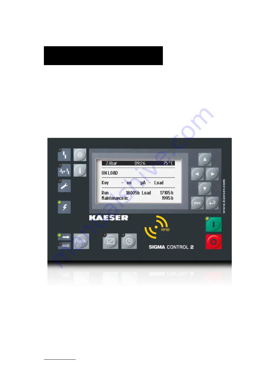
background image


User Manual 

Controller  

SIGMA CONTROL 2  

 SCREW FLUID ≥5.0.X 

No.: 9_9450 12 E

Manufacturer:

KAESER KOMPRESSOREN SE

96410 Coburg • PO Box 2143 • GERMANY • Tel. +49-(0)9561-6400 • Fax +49-(0)9561-640130
www.kaeser.com

Summary of Contents for SIGMA CONTROL 2

Page 1: ...User Manual Controller SIGMA CONTROL 2 SCREW FLUID 5 0 X No 9_9450 12 E Manufacturer KAESER KOMPRESSOREN SE 96410 Coburg PO Box 2143 GERMANY Tel 49 0 9561 6400 Fax 49 0 9561 640130 www kaeser com...

Page 2: ...KKW SSC 2 12 en IBA SIGMA CONTROL FLUID KKW SSC 2 12 20210526 085236...

Page 3: ...and options 16 3 2 2 Indicator elements and interfaces 17 3 2 3 Technical specifications 17 4 Safety and Responsibility 4 1 Basic instructions 19 4 2 Specified use 19 4 3 Improper use 19 5 Design and...

Page 4: ...2 16 Setting the time server 75 8 3 KAESER CONNECT benefits 76 8 3 1 Open KAESER CONNECT 76 8 3 2 System status menu 78 8 3 3 Graphs menu 79 8 3 4 Messages menu 81 8 3 5 I O display menu 82 8 3 6 Use...

Page 5: ...ated by pressure switch 147 8 11 9 Examples of time settings for equal overall load 152 8 12 Setting input and output signals 153 8 12 1 Output operational states of machine on digital outputs 153 8 1...

Page 6: ...0 10 6 Interpreting system messages 230 10 7 KAESER i Box Operating states and troubleshooting 231 11 Maintenance 11 1 Replacing the battery 232 12 Spares Operating Materials Service 12 1 Note the nam...

Page 7: ...s 80 Fig 24 Messages illustration similar 82 Fig 25 I O display illustration similar 83 Fig 26 User management menu 84 Fig 27 Log on for write access window 84 Fig 28 User management menu 85 Fig 29 Se...

Page 8: ...List of Illustrations vi User Manual Controller SIGMA CONTROL 2 SCREW FLUID 5 0 X No 9_9450 12 E...

Page 9: ...rating elements 22 Tab 28 Display elements 23 Tab 29 RFID reader 24 Tab 30 Data in the header depending on the machine type 25 Tab 31 Reset check box status 27 Tab 32 Check box status 27 Tab 33 KAESER...

Page 10: ...9 pole interface on the PROFIBUS module 126 Tab 72 Master slave settings 134 Tab 73 Function diagram 150 Tab 74 Example for a clock program for equal duty cycling during the day 152 Tab 75 Example for...

Page 11: ...nu option Exits editing mode and saves 7 ON Switches the machine on 8 OFF Switches the machine off 10 RFID RFID reader for logging user in via RFID Equipment Card 11 Time control Switches time control...

Page 12: ...15 LOAD Illuminates continuously in green when the machine is running in LOAD 16 Voltage applied to controller Illuminates continuously in green when voltage is supplied to the con troller 17 Warning...

Page 13: ...alve temperature sensor for excessive temper ature shutdown 10 Components Displays machine component settings e g power switching Tab 3 Main menu overview See chapter 5 7 2 for the complete menu struc...

Page 14: ...ee chapter 9 13 Alarm messages 1 1 1 An alarm message shuts the machine down The Alarm LED flashes red Alarm messages are identified by the letter A Ex ample 0002 S k 31 12 17 13 14 15 Motor temperatu...

Page 15: ...entered following log in with an RFID Equipment Card providing access level 2 1 SIGMA CONTROL 2 Quick reference guide 1 4 Functions overview No 9_9450 12 E User Manual Controller SIGMA CONTROL 2 SCRE...

Page 16: ...ROL 2 contains copyright protected software packages which are licensed as Open Source A copy of these licenses is contained in SIGMA CONTROL 2 Display the licenses by pointing your browser to the COP...

Page 17: ...rules The operation is subject to the following two conditions this device may not cause harmful interference and this device must accept any interference received including interference that may cau...

Page 18: ...cedure and numbered as a step Example 1 WARNING The type and source of the imminent danger is shown here The possible consequences of ignoring a warning are shown here The word WARNING indicates that...

Page 19: ...or spare parts Precondition Here you will find conditional requirements necessary to carry out the task The conditions relevant to safety shown here will help you to avoid dangerous situations This s...

Page 20: ...l System Input Output MCSIO Digital and analogue inputs and outputs integrated Input Output Module IOM Modules with digital and analogue inputs and out puts 1 only SIGMA CONTROL 2 FLUID Tab 8 Versions...

Page 21: ...ket X2 I O bus 9 pole SUB D pins X3 RS485 FC USS interface 9 pole SUB D socket X4 Com modules slot for communications module Module optional for PROFIBUS PROFINET Modbus RTU Modbus TCP DeviceNet Ether...

Page 22: ...current 0 20 mA AII1 00 AII1 01 Analogue input resistor AIR1 00 AIR1 01 X10 DOR Digital output relay 250 VAC 4 A DOR1 00 DOR1 04 The positions of the interfaces X1 X10 are marked on the rear of the c...

Page 23: ...Cable length m Analogue input current AII Analogue input resistor AIR Analogue output current AOI 30 Digital input DI Digital output relay DOR 100 Digital output transistor DOT 30 Tab 15 Cable lengths...

Page 24: ...compres sor interior Digital input DI 24 VDC 6 2 Analogue input current AII 0 20 mA 1 2 Analogue input resistor AIR PT100 3 Digital output relay DOR 250 VAC 8 A 4 Digital output transistor DOT 24 VDC...

Page 25: ...tput current AOI 30 Digital input DI Digital output relay DOR 100 Digital output transistor DOT 30 Tab 20 Cable lengths 3 1 4 3 Input output modules degree of protection Characteristic Value Degree of...

Page 26: ...ailable in various technical versions Option Material number Type Ex works installation 7 7822 00130 Modem i Box EMEA Europe Middle East and Africa 7 7822 00140 Modem i Box NA North America 7 7822 001...

Page 27: ...ical specifications Type Characteristic Value Electrical data Rated voltage V 24 10 Rated current A 0 15 Continued run time in case of power outage s 10 Mechanical data Height x width x length mm 45 x...

Page 28: ...2 B13 700 3G bands B2 1900 B5 850 LATAM type 4G bands B1 B2 B3 B4 B5 B7 B28 3G bands B1 B2 B4 B5 Ethernet LAN 3 x RJ45 10 100Base TX USB Mini USB socket USB 2 0 for service purposes only Antenna SMA F...

Page 29: ...m ages that may result from incorrect use The user alone is liable for any risks incurred Adhere to the specifications given in these operating instructions and the machine s service manual Operate th...

Page 30: ...it display touch keys LEDs and interfaces Radio Frequency Idenfication RFID Identification with RFID Equipment Card Slot for customer interface optional communications module SD card slot for SD SDHC...

Page 31: ...2 Connection to con trol technology not provided 6 Inputs outputs in the interior of the control cabinet 7 Inputs outputs in the interior of the com pressor 8 Inputs outputs for external sensors 9 Com...

Page 32: ...1 Up Scrolls up the menu options Increases a parameter value 2 Left Jumps to the left Moves the cursor position to the left 3 Right Jumps to the right Moves the cursor position to the right 4 Down Scr...

Page 33: ...Display Graphic display with 8 lines and 30 characters per line 11 Time control Continuous green light when the machine is controlled by the timer 12 Remote control Continuous green light when the mac...

Page 34: ...the ma chine Typical application Operators log on at the machine Manual input of the password not required The RFID Equipment Cards are carefully packed in a plastic sleeve This plastic sleeve is atta...

Page 35: ...re Time Airend discharge temper ature SIGMA CONTROL 2 BLOWER p2 final pressure Time Discharge temperature T2 SIGMA CONTROL 2 BOOSTER Pressure at the com pressed air inlet p1 Temperature at the compres...

Page 36: ...d by the access level and some menus are displayed or hidden due to specific settings or options For example you can recognise subordinate menus in the menu structure by the number preced ing their de...

Page 37: ...de The check box will flash You then press Up The check box is activated and flashes Press again Enter to save the settings The display line no longer flashes and the key is activated Proceed correspo...

Page 38: ...f the control ler This enables for example the operating and energy efficiency of your machine to be checked remotely To do so you must generate a one time password see Chapter 8 2 5 KAESER CONNECT do...

Page 39: ...in and other procedures please see Chapter 8 3 5 6 KAESER i Box The KAESER i Box is a data transmission component for machines equipped with the SIGMA CONTROL 2 It is arranged between the KAESER cont...

Page 40: ...itched on details of the software are displayed Example Compressor Machine model PN SN Material number and serial number of the machine EN Equipment number of the machine SIGMA CONTROL 2 MCS MCS Main...

Page 41: ...of the machine being in LOAD mode 5 7 2 Menu structure Press Enter or one of the arrow keys to open the main menu In the main menu you can Retrieve displayed information Enter customer specific setti...

Page 42: ...nt 1 4 UzK 1 4 Torque 1 4 Reference value 1 4 Fan motor s Oil cooler fan Speed 1 4 Current 1 4 UzK 1 4 Torque 1 4 Air cooler Fan Speed 1 4 Current 1 4 UzK 1 4 Torque 1 4 Analogue values SIGMA CONTROL...

Page 43: ...hanged Valve inspection Belt coupling inspection Compressor motor Bearing lube Bearing change Fan motor s Bearing lube Bearing change Electrical equipment Annual maintenance due 5 Configuration For de...

Page 44: ...thernet SIGMA NETWORK Com Module 3 Key remote For details of the Communication menu please see table 39 9 Machine test T V inspection 10 Components Compressor motor Power switching For details of the...

Page 45: ...starts per hour Motor starts T Last load run Last idle run 12 Last motor off 1 3 Current pressure control SIGMA CONTROL 2 Cut out pressure SP SD Network actual pressure Frequency converter 1 4 Setpoi...

Page 46: ...I DO display 3rd I O module DI DO display 1 6 pN ADT curve Diagram Nominal pressure airend discharge temperature 1 7 pN n curve 1 4 Diagram Nominal pressure Speed 1 Power switching with frequency conv...

Page 47: ...essor motor 1 4 Oil air cooler fan 1 4 Oil cooler fan 1 4 Air cooler Fan 1 4 Model Date time Time zone Time server active IP address Date format Time format Pressure unit Temperature unit Display ligh...

Page 48: ...e 5 5 Acknowledgement Remote mode RC Ack Key remote 5 6 ETM 4 12 Heat recovery Local mode Remote mode current RC DI Key remote Heat recovery ADT controller Thermostat valve Oil cooler Thermostat valve...

Page 49: ...air supply Safe compressed air quality Error operation without RD active Run time max Reset Alarm 5 10 PD temperature controller Nominal value 13 Actual value 13 Controller parameter 13 KP KI KD Actua...

Page 50: ...igation Function submenu 5 2 1 Pressure sensors System pressure pNloc Internal pressure pi 5 2 2 Pressure settings System pressure high 5 pRV Safety valve actuating pressure 4 Pressure rise 4 12 pE SP...

Page 51: ...e 12 5 2 4 Network actual pressure pNloc local network pressure FC USS 1 4 AII AII For sensor error Type of message Warning Alarm 1 Power switching with frequency converter 4 SIGMA CONTROL 2 FLUID 5 S...

Page 52: ...On load DOR DOT Group alarm DOR DOT Group warning continuous DOR DOT Group warning interrupted DOR DOT Remote mode DOR DOT Clock active DOR DOT Clock contact DOR DOT EMERGENCY STOP DOR DOT 1 Power swi...

Page 53: ...uts 4 AO_p_1 AO_p_2 AO_T_1 AO_T_2 AO_I_1 AO_I_2 AO_n_1 1 PD Process data PD_p_1 PD_p_2 PD_T_1 PD_T_2 PD_I_1 PD_I_2 5 7 3 External messages External message 1 External message 2 External message 3 Exte...

Page 54: ...ADT Inlet temperature PD temperature n Compressor motor 1 4 1 Power switching with frequency converter 4 SIGMA CONTROL 2 FLUID 12 not for SXC Tab 38 I O periphery menu 5 Design and Function 5 7 Menu...

Page 55: ...Connections menu please see table 40 E mail active Compressor number Language Repeat cut off time Use SSL Sender address Sender name Contact telephone Receiver address SMTP Server User name Password...

Page 56: ...CONTROL 2 FLUID Tab 39 Communication menu 5 7 2 4 Connections menu Navigation Function Submenu 8 1 2 Connections SIGMA CONTROL 2 4 Status Mode Port Communication partner IP address Communication erro...

Page 57: ...le 42 1 Power switching with frequency converter 3 SIGMA CONTROL 2 Prepared for connection to control centre 4 SIGMA CONTROL 2 FLUID 6 Power switching with frequency converter and speed sensor is bein...

Page 58: ...ady Mains contactor SFC USS 4 USS status Run Error Run up period 1 Service operation 1 Heavy load monitoring 1 Mains contactor 1 STO channel A 1 STO channel B 1 Softstart 4 ready Motor running Start u...

Page 59: ...nsor error 7 Operating mode 7 Scaling 4mA 20mA 1 Speed set point manual 11 nMin nMax 11 Nominal value 11 Actual values 7 Target Actual 7 1 Power switching with frequency converter 4 SIGMA CONTROL 2 FL...

Page 60: ...less power The inlet valve is closed The minimum pressure check valve isolates the oil separator tank from the air system The venting valve is open A small volume of air circulates through the bypass...

Page 61: ...er requires two times to be specified The minimum run time and the off time The shorter these times are set the sooner and more frequently the motor engine is stopped VARIO The VARIO mode is based on...

Page 62: ...the machine reverts to the selected control mode DUAL The minimum controllable speed is reached and the machine switches to IDLE mode The drive engine runs unloaded with low power consumption When the...

Page 63: ...delivers com pressed air to the distribution network The load and power consumption of the drive motor rises and falls with the air demand To ensure optimal control on large compressors the control a...

Page 64: ...the machine into which the controller is installed NOTICE UV radiation Direct sunlight UV radiation can destroy the display screen Do not allow the display screen to be subjected to direct sunlight S...

Page 65: ...suggestions Remote control Risk of injury caused by unexpected starting Before starting make sure that no one is working on the machine and that it can be safely started Tab 44 Remote control identif...

Page 66: ...al Management 8 9 Refrigeration dryer 8 10 Setting the machine for local mode 8 11 Setting the machine for master control operation 8 12 Input and output signals 8 14 Activating remote acknowledgement...

Page 67: ...t and the brightness 8 2 13 Activating the remote control 8 2 14 IP configuration 8 2 15 Setting the e mail function 8 2 16 Setting the time server 8 3 6 Creating a user account 8 2 1 Selecting menu o...

Page 68: ...machine type Date time 7 Use the Up or Down key to select a menu item in the General menu such as System information 8 Press Escape repeatedly to leave this menu 8 2 2 Setting the language You can cho...

Page 69: ...6 1bar 08 15AM 80 C Header Main menu English GB Active line with current set language 1 Status Submenu 2 Performance data Submenu 3 Operating data Submenu 4 Maintenance Submenu 5 Configuration Submenu...

Page 70: ...password you can manually log on to SIGMA CONTROL 2 see chapter 8 2 5 8 2 4 User log in with RFID Equipment Card The RFID Equipment Card enables an easy and quick log in at SIGMA CONTROL 2 It authori...

Page 71: ...OL 2 A password is also required to use KAESER CONNECT to log on at SIGMA CONTROL 2 see chapter 8 3 Prerequisite for this is that you know your Name Password You have noted your user name and stored i...

Page 72: ...itable location if it should become necessary to manually log on without RFID Equipment Card 5 Press Enter The setting is applied 8 2 6 Manual user log in In the event that your RFID Equipment Card is...

Page 73: ...ct the Login line 12 Press Enter Current access level 2 is displayed Result You are now logged on to SIGMA CONTROL 2 with access level 2 having manually input your user name and the password 8 2 7 Cre...

Page 74: ...7326 Level 2 3 Repeat the above steps at the next machine if the master RFID Equipment Card is to be regis tered at other machines Result You have registered a master RFID Equipment Cards at the machi...

Page 75: ...ss Enter The setting is applied 12 Press Escape repeatedly to leave this menu Check set the date Precondition Access level 2 is activated 1 Open the 5 1 Configuration General menu 2 Use Up or Down to...

Page 76: ...ce 6 1bar 08 15AM 80 C Header 5 1 General Menu Model XXXXXX set machine type Date time 04 13 21 08 15 37AM Europe London Time zone 4 Press Enter The time zone display flashes 5 Use Up or Down to set t...

Page 77: ...Setting the time format Set the display for the time format Format Example hh mm ss 13 33 45 hh mm 13 33 hh mm ssAM PM 01 33 45PM hh mmAM PM 01 33PM Tab 48 Possible settings for the time format Precon...

Page 78: ...unit Precondition Access level 2 is activated 1 Open the 5 1 Configuration General menu 2 Use Up or Down to select the Pressure unit line 6 1bar 08 15AM 80 C Header 5 1 General Menu Time format hh mm...

Page 79: ...splay for the set unit flashes 4 Use Up or Down to set the unit 5 Press Enter The setting is applied 6 Press Escape repeatedly to leave this menu 8 2 11 Setting the display illumination Set the displa...

Page 80: ...he contrast and the brightness Contrast and brightness are factory set to normal light conditions You can manually set contrast and brightness for different lighting conditions Precondition The operat...

Page 81: ...control is activated 8 2 14 IP configuration For the SIGMA CONTROL 2 to be connected to the network you must set the IP configuration for KAESER CONNECT for example If you use SIGMA CONTROL 2 as the m...

Page 82: ...is displayed 10 Set the remaining network parameters as described above Parameters Setting value Meaning IP address IP address of the interface X1 Ethernet Subnet mask Subnet mask of the network Gatew...

Page 83: ...parameters are known Request the required information from the IT department 1 Open the 8 1 3 Communication Ethernet SIGMA NETWORK E mail menu 2 Use Up or Down to select the active line 6 1bar 08 15AM...

Page 84: ...of the sender in this field Sender name Enter the name of the sender in this field Contact telephone In this field enter a telephone number under which the air station oper ator can be reached This te...

Page 85: ...ting the time server function IP address 192 053 103 103 Example address time server 3 Press Enter The first group of numbers of the IP address flashes 192 053 103 103 4 Use Up or Down to set the firs...

Page 86: ...Remotely setting parameters For KAESER CONNECT to be able to use the Internet capable device it must be registered in the same network as SIGMA CONTROL 2 To be able to use KAESER CONNECT the browser...

Page 87: ...Click Login KAESER CONNECT for SIGMA CONTROL 2 is displayed Fig 18 KAESER CONNECT for SIGMA CONTROL 2 6 Click the arrow key 1 to open Select language The Select language window is displayed 8 Initial...

Page 88: ...Result KAESER CONNECT is displayed in the set language 8 3 2 System status menu Precondition KAESER CONNECT for SIGMA CONTROL 2 is displayed Fig 20 System status menu 1 Click the System status menu e...

Page 89: ...nd display the automatically recorded machine data for any time in the past Moving the mouse pointer across the graph calls up a ruler The time selected with the ruler and the associated values are di...

Page 90: ...Description Function 1 Start Display the oldest data in the cache memory or load the data from the previ ous 20 minutes from the SD card 2 Scroll left Shift the display area by 1 3 to the left 3 Zoom...

Page 91: ...ndition An SD card with sufficient free memory is inserted in the X5 SD card slot The SD card was inserted for the entire operating time of the machine The SIGMA CONTROL 2 data recorder function is ac...

Page 92: ...sured values of the analogue inputs and the states of the digital inputs and outputs are displayed in the I O display menu Depending on the machine options you may select from further IOM module tabs...

Page 93: ...rd Subsequently the write mode is activated see Chapter 8 2 5 The write mode is granted only to one person at a time If a second user attempts to log on in write mode he will be refused by the system...

Page 94: ...r write access window is displayed Fig 27 Log on for write access window 3 Enter your user name in the User name field 4 Enter your password in the Password field 5 Click OK The User management menu i...

Page 95: ...ed and activated Editing a user account You can edit existing user accounts Changing the password Changing the access level Changing the status Example Change the password for an existing user account...

Page 96: ...NECT for SIGMA CONTROL 2 is displayed 1 Click the Settings menu element 2 Click the arrow key for the unit of pressure A selection list of units of pressure is displayed 3 Set the appropriate pressure...

Page 97: ...e Backup menu element Fig 30 Backup menu 2 Set the required backup type in the Select source option 3 Click Backup Result The data are downloaded to the Internet capable device 8 3 9 Data recording me...

Page 98: ...ig 31 Data recording menu 2 Select the option Hour file or Start time 3 Set the desired time in the fields MM DD YY and HH 00 4 Click on Get Data Result The data is downloaded onto the device The down...

Page 99: ...int for pressure increase upper safety limit for maximum machine pressure in an external LOAD controller this value is used to switch the machine from LOAD to IDLE 12 in the event of a fault pE SD Swi...

Page 100: ...for SXC Tab 55 Compressor pressure parameters Set the parameters according to the following specifications 8 5 1 Displaying pressure parameters Precondition Access level 2 is activated Open the menu...

Page 101: ...under the following condition Network pressure SP pA pB switching differential Tab 57 Pressure condition for LOAD The machine switches to IDLE under the following conditions 12 Network pressure Netwo...

Page 102: ...s triggered The parameter for pE SP pressure increase is pre set and cannot be changed You can however adjust the SD switching differential not for SXC Displaying and adjusting the pressure increase p...

Page 103: ...w 5 0bar SD 0 50bar current network pressure low point ta 600s DOR1 03 Logic Cut in pressure min 5 0bar 3 Press Enter The setting mode is active 4 Use Up or Down to set the value for System pressure l...

Page 104: ...s can press the IDLE key without the machine switch ing to IDLE 8 6 Machine start and machine stop In addition to manually starting the machine locally you have the following alternatives Function Sta...

Page 105: ...ompressor clock Menu Key clock The time control key is activated Reset All current switching points are reset 01 n a 00 00AM off Active line 02 n a 00 00AM off 03 n a 00 00AM off User defined clock pr...

Page 106: ...2 Mon Fri 12 00PM off 03 Mon Fri 01 00PM on 04 Mon Thu 05 00PM off 05 Fri 03 00PM off Tab 63 Example of a machine ON OFF clock program Precondition Access level 2 is activated 1 Open the 6Compressor c...

Page 107: ...r On action 16 Press Enter The setting is applied The Compressor ON action is set for the first switching point 17 Set the other switching points in the same manner Result Weekdays time and the Compre...

Page 108: ...ly repeating settings of the time control you can also set a longer lasting shut down time For company shut down see the time as follows Precondition Access level 2 is activated 1 Open the 5 4 2 Confi...

Page 109: ...e 6 1bar 08 15AM 80 C Header 5 4 2 Compressor off Menu Holidays Active line Start 12 23 21 Date for start 05 00PM Time for start End 01 04 22 Date for end 06 30AM Time for end 18 Press Enter The check...

Page 110: ...e with the input signal from the remote control centre Variant B Starting the machine from the remote control centre in addition to a configured ON OFF clock program The machine can be started from th...

Page 111: ...ult Logic Key remote Key clock 2 Press Enter The display for the currently set input flashes 3 Select another input with the Up or Down keys 4 Press Enter The input has now been assigned 5 Press the R...

Page 112: ...1 01 21 00 00AM End 01 01 21 3 Press Enter The check box Venting period will flash 4 Press UP The check box is deactivated 6 1bar 08 15AM 80 C Header 5 4 2 Compressor off Menu Venting period Active li...

Page 113: ...ay time Setting the auto start delay time If you operate several machines it is better to start them in sequence Use the Delay time for auto start table to plan the time delayed machine start In the S...

Page 114: ...ing delay time 3 Press Enter The Target display flashes 4 Use Up or Down to set the time delay in seconds 6 1bar 08 15AM 80 C Header 5 4 Compressor start Menu 1 Compressor on Active line 2 Compressor...

Page 115: ...compressors it is not possible to set the control modes since there is no IDLE operating point All menus connected to it are then not available The controller is provided with various control modes th...

Page 116: ...e 6 Press Enter The setting is applied 7 Press Escape repeatedly to leave this menu 8 7 2 Setting the DUAL control mode The machine switches to the READY operating point when the specified idle time h...

Page 117: ...When the minimum running period has elapsed the machine switches from IDLE to READY The expired duration of the unloaded period controls whether the machine switches from IDLE to READY only after exp...

Page 118: ...Type Electronic thermal management ETM Machine type 1 Without heat recovery Machine type 2 Heat recovery without electrically controlled valve Machine type 3 Heat recovery with adjustable airend disc...

Page 119: ...line current inactive Status of heat recovery 3 Press the DOWN key 4 Press Enter The currently active operating mode flashes 5 Use Up or Down key to set the active option 6 Press Enter The setting is...

Page 120: ...ETM menu 2 Use Up or Down to select the Local mode line 6 1bar 08 15AM 80 C Header 5 6 ETM Menu Heat recovery Local mode inactive Active line Remote mode inactive current inactive Status of heat recov...

Page 121: ...oller Active line 1 Oil cooler Indication 2 ADT controller Indication 3 Press Enter The setting mode is active 4 Use Up or Down to set the setpoint for the ADT controller 6 1bar 08 15AM 80 C Header 5...

Page 122: ...via a timer if compressed air is not required With this control mode activated the operating temperature in the refrigeration dryer will be kept within narrow limits via a cycling of the refrigeratio...

Page 123: ...temperature of the refrigeration dry er as a binary signal You can assign to DOR or DOT If you have parametrised correctly OK will be displayed Precondition Access level 2 is activated 1 Open the men...

Page 124: ...Upon activation of the check box err is displayed The parametrisation is incorrect Deactivate the check box Assign a different free output 8 9 3 Refrigeration dryer alarm Compressed air quality has p...

Page 125: ...he compressed air supply has priority over compressed air quality Access level 2 is activated 1 Open the menu 5 9 Configuration Refrigeration dryer 2 Using the Up or Down key select the line Error ope...

Page 126: ...he controller of fers the following modes of operation Operating mode Description See chapter pA The machine is controlled by the nominal pressure pA 8 10 3 3 pB The machine is controlled by the nomin...

Page 127: ...05 06 07 08 09 10 Tab 67 User defined timing program for nominal pressure change When setting a clock programme for the first time note first the switching times on the User defined clock program tab...

Page 128: ...pB Clock line 3 Press the Enter key The Timing program menu is displayed 4 Use the Up or Down keys to select the Reset line 6 1bar 08 15AM 80 C Header 5 2 3 1 pA pB Clock Menu Reset Active line 01 Mon...

Page 129: ...kdays 4 Press the Enter key The setting is applied 5 Press the Right key 6 Press the Enter key The display for hours 00 00 flashes 7 Use Up or Down to set the hours 8 Press the Right key 9 The mnutes...

Page 130: ...s to select the pA pB Cycle line 3 Press the Down key The pA line is displayed 4 Press Enter The display for the cycle duration in hours 00 flashes 5 Use Up or Down to set the hours 6 Press the Enter...

Page 131: ...s level 2 is activated The timing program or timer is set up 1 Open the 5 2 3 Configuration Pressure control Load control menu 2 Use the Up or Down keys to select the Local mode line 3 Press the Enter...

Page 132: ...ontrol via a LOAD remote contact is another method of control ling the machine externally LOAD remote contact 12 An input signal from a master controller switches the machine to LOAD or IDLE The nomin...

Page 133: ...rt network 3 Set the IP address for SIGMA CONTROL 2 using the following pattern 169 254 100 SAM 4 0 machine number 102 for the setting see chapter 8 2 14 Setting SAM 4 0 mode The IP address for SAM 4...

Page 134: ...tart td 15s active line Timeout 5s 11 Press Enter The setting mode is active 12 Use Up or Down to set the Start td value to 30 s 6 1bar 08 15AM 80 C Header 8 1 2 2 SAM 4 0 Menu IP address 169 254 100...

Page 135: ...the data exchange Activate the Communication error check box to enable monitoring for communication malfunctions 6 1bar 08 15AM 80 C Header 8 1 2 2 SAM 4 0 Menu IP address 169 254 100 100 Port 2000 Co...

Page 136: ...Tab 71 Pin assignment of SUB D 9 pole interface on the PROFIBUS module Interface connector wiring Fig 32 Wiring of the PROFIBUS connection 1 Terminal 1A 2 Terminal 1B 3 Terminal 2A 4 Terminal 2B 5 Sl...

Page 137: ...SIGMA AIR MANAGER extract Fig 33 Electrical diagram example with SIGMA AIR MANAGER 8 Initial Start up 8 11 Setting the machine for master control operation No 9_9450 12 E User Manual Controller SIGMA...

Page 138: ...rear of the SIGMA CONTROL 2 Material Small screwdriver Torx screwdriver size 9 Precondition The machine is disconnected from the power supply The absence of voltage has been verified Work with caution...

Page 139: ...when its front plate 3 sits tightly in the recess of shaft inter face X4 1 3 Use the Torx T9 screwdriver to screw in the fixing screws 4 to hand tightness 8 11 3 2 Activating operation via PROFIBUS Ov...

Page 140: ...ar 08 15AM 80 C Header 8 2 Com Module Menu Status Counter 1 Com Module deactivated Type None Send receive Com Module active Active line 4 Press the Up key The check box is activated 5 Press Enter The...

Page 141: ...or 2 Use Up or Down to select the SlaveNo line 6 1bar 08 15AM 80 C Header 8 2 Com Module Menu Send receive Com Module active Reset Slave No 103 Active line Communication error 3 Press Enter The displa...

Page 142: ...tings for SIGMA AIR MANAGER without SIGMA AIR CONTROL PLUS Start 30 seconds Settings for SIGMA AIR MANAGER with SIGMA AIR CONTROL PLUS Start 40 seconds 1 Use Up or Down to select the Communication err...

Page 143: ...e pA pB SC2 At peak air demand times pressure is regulated to the pB set point pressure and at times with low air demand to set point pressure pA At times with lower compressed air demand the machine...

Page 144: ...two machines with SIGMA CONTROL 2 in interconnected operation both controllers must be equipped with the same software version Follow the configuration steps as described in table 72 Controller Proced...

Page 145: ...nstall the Ethernet cable between the two machines When you connect the machines to a network LAN or switch when using KAESER CONNECT for example Install the Ethernet cable from each machine to the LA...

Page 146: ...SD 0 5bar System pressure low 5 0bar SD 0 50bar 3 Use Up or Down to set the pA value 4 Press Enter The setting is applied 5 Press Down The pB line is displayed 6 If necessary adjust the value for the...

Page 147: ...pB Cycle Master IP configuration The controllers of both machines must be set to different IP addresses Example IP addressController machine 1 Master mode 169 254 100 101 IP address Controller machin...

Page 148: ...ied Result The controller of machine 1 is set as master 8 11 4 3 Setting the machine 2 controller as slave Precondition The electrical connection is made Access level 2 is activated Setting the switch...

Page 149: ...rol Menu Local mode pA pB Cycle Remote mode pA pB SC2 Active line current operating mode 1 pA pB Clock pA pB Cycle 4 Use Up or Down to set the pA pB SC2 input 5 Press Enter The setting is applied Slav...

Page 150: ...s Enter The setting is applied Result The controller of machine 2 is set as slave 8 11 5 Configuring interconnected operation using the LOAD remote contact e g SIGMA AIR MANAGER BASIC 3 Overview Estab...

Page 151: ...contact Precondition Access level 2 is activated Set the LOAD remote contact operating mode 1 Open the 5 2 3 Configuration Pressure control Load control menu 2 Use Up or Down to select the Remote mod...

Page 152: ...Press Enter ok is displayed to the left of the check box The operating mode is set 8 11 5 3 Setting the SD switching differential of the pressure increase Set the SD switching differential of the pres...

Page 153: ...act Fig 39 Wiring diagram for local LOAD remote contact A Changeover between automatic and manual modes B LOAD IDLE contact Make the electrical connection according to the diagram 8 11 6 2 Set the loc...

Page 154: ...ad RC DI1 06 ok Logic loc load RC DI1 07 Active line 3 Use Up or Down to select a new input for local LOAD remote contact 4 Press Enter The input for local LOAD remote contact is assigned 8 11 6 3 Set...

Page 155: ...d 8 11 6 5 Assign an input for the LOAD remote contact for switching the pressure control Precondition Access level 2 is activated 1 Open the 5 2 3 Configuration Pressure control Load control menu 2 U...

Page 156: ...level 2 is activated 1 Open the 5 2 3 Configuration Pressure control Load control menu 2 Use Up or Down to select the Remote mode line 3 Press Enter The currently active operating mode flashes 6 1bar...

Page 157: ...e clock program or clock on SIGMA CONTROL 2 Select local mode with time control pA pB Clock or clock pA pB Cycle Select the network nominal pressures pA and pB analogous to the required values They mu...

Page 158: ...the diagram Set the network nominal pressure pA and pB Precondition Access level 2 is activated The electrical connection is made 1 Open the 5 2 2 Pressure control Pressure settings menu see chapter...

Page 159: ...figuration Pressure control Load control menu 2 Use Up or Down to select the pA pB DO line 6 1bar 08 15AM 80 C Header 5 2 3 Load control Menu pA pB RC DI1 10 Logic pA pB DO DOR1 03 Active line no outp...

Page 160: ...ing point of the SK machine s pressure switch to be in between When pB is activated for the periods of low demand the SK machine automatically functions as the base load machine Set the required value...

Page 161: ...t Time Set the network nominal pressure pA and pB Precondition Access level 2 is activated 1 Open the 5 2 2 Pressure control Pressure settings menu see chapter 8 5 1 2 Use Up or Down to select the pA...

Page 162: ...riggers the switch between network nominal pressure pA and network nominal pressure pB local operating mode pA pB Cycle local mode Precondition The network nominal pressure pA pB is configured the sam...

Page 163: ...Output operational states of machine on digital outputs 8 12 2 Output input signals on the display 8 12 3 Output measured values on the display 8 12 4 Switching and or triggering messages with thresho...

Page 164: ...ether the EMERGENCY STOP command device has been actuated 12 not for SXC Tab 76 Assigned output signals 8 12 1 1 DO functions menu The requested message can be assigned to a free digital output DOR or...

Page 165: ...play In addition to the defined alarm and warning messages there are six further freely selectable input signals that can be used to display messages A list of the alarm and warning messages is provi...

Page 166: ...the External message 1 line 2 Press Enter The External message 1 menu is displayed 6 1bar 08 15AM 80 C Header 5 7 3 1 External message 1 Menu External message 1 Message text DI1 06 No input assigned t...

Page 167: ...the input flashes 7 Press the Up key The check box is activated 6 1bar 08 15AM 80 C Header 5 7 3 1 External message 1 Menu External message 1 Message text DI1 07 ok Input selected td 0s Logic Logic D...

Page 168: ...lect the td line 2 Press the Right arrow 3 Press Enter The control field Logic flashes 4 Use UP or Down to set the desired behaviour see table 77 6 1bar 08 15AM 80 C Header 5 7 3 1 External message 1...

Page 169: ...Header 5 7 3 1 External message 1 Menu External message 1 Message text DI1 07 ok Input selected td 0s Logic active line set logic control field DOR1 01 Output is selected and activated Warning Exampl...

Page 170: ...e current value I2 T Switch inlet temperature Customised monitoring of the intake temperature p Switch pi Customised monitoring of internal pressure pi in the oil sep arator tank T Switch ADT Customis...

Page 171: ...lue 2 AnMod_p_2 3 AnMod_p_3 4 AnMod_p_4 5 AnMod_T_1 6 AnMod_T_2 3 Use Up or Down to select the AnMod_p_1 line 4 Press Enter The 5 7 2 1 1 AnMod_p_1 menu is displayed 6 1bar 08 15AM 80 C Header 5 7 2 1...

Page 172: ...tle 0 0 bar Message text pNloc selected analogue measured value SP 8 0bar SD 0 5bar Switching point SP and switching differential SD td 0s Time delay td 5 Press the Right arrow 6 Press Enter The check...

Page 173: ...Set the time delay The delay can be set between 0 and 600 seconds The delay is counted down from 600 in 1 second increments with the DOWN key and counted upwards from 0 zero in 1 second increments wi...

Page 174: ...e output By triggering the message one or two digital DOR outputs can be switched 1 Use Up or Down to select the DOR line 2 Press Enter The DOR output display flashes 3 Select the output with the Up a...

Page 175: ...pressure System pressure pNloc lo cal network pressure at compressor output 0095 O W A Internal pressure pi Threshold for pressure Internal pressure pi internal pressure pi in the oil separator tank 0...

Page 176: ...c DOR1 01 Output DOR Operation Type of message 8 12 4 1 Setting the switching point and switching differential 1 Use Up or Down to select the SP line 6 1bar 08 15AM 80 C Header 5 7 4 1 System pressure...

Page 177: ...lt The td delay time has been set 8 12 4 3 Assign and activate the output Once the threshold has been reached you can switch a digital output DOR 1 Use Up or Down to select the DOR line 2 Press Enter...

Page 178: ...ow 6 Press Enter The check box assigned to the message type flashes 7 Press Up key The message is activated 8 Press Enter Result The message type is set and activated 8 12 4 5 Activating the threshold...

Page 179: ...lectrical connection has been established for information about a spare DOR output please see the machine s wiring diagram 1 Open the 5 8 Configuration Timer menu 6 1bar 08 15AM 80 C Header 5 8 Timer...

Page 180: ...ne underneath 8 14 Activating remote acknowledgement When fault or warning messages are routed to a remote control centre via an output it makes sense to have these messages acknowledged by the contro...

Page 181: ...ress Enter The currently active operating mode flashes 5 Use Up or Down to set the Key remote contact input 6 1bar 08 15AM 80 C Header 5 5 Acknowledgement Menu Remote mode Key remote contact Active li...

Page 182: ...signed to the input flashes 7 Press the Up key The check box is activated 8 Press Enter The input is assigned and activated 6 1bar 08 15AM 80 C Header 5 5 Acknowledgement Menu Remote mode Key remote c...

Page 183: ...ransducer pNloc remains active Overview Example The external pressure transducer is connected to SIGMA CONTROL 2 Open the Configuration Pressure control menu Assigning an input 8 15 1 Pressure control...

Page 184: ...essure Menu AII 6 1bar Active line AII1 01 ok 0 0bar For sensor error Alarm 7 Press UP The check box is activated ok is displayed 8 Press Enter The setting is applied Result The input for the external...

Page 185: ...uminate 6 1bar 08 15AM 80 C Header Load Current operating mode Key on pA on Operating parameters Run 2500h Load 2490h Operating parameters Maintenance in 500h Maintenance indicator 2 Continue the comm...

Page 186: ...stallation and Operating Conditions are met 1 Switch on the user s power supply isolating device 2 Switch on the machine and wait for SIGMA CONTROL 2 to start The voltage applied to controller LED 16...

Page 187: ...gain 9 2 Switching off in an emergency The EMERGENCY STOP command device is located below the controller 2 2 Does not apply to i Comp Fig 43 Switching off in an emergency 22 EMERGENCY STOP command dev...

Page 188: ...Message coming LED flashes Message acknowledged LED illuminates Message going LED off Tab 82 Message sequence 1 Message sequence 2 Indication Message coming LED flashes Message going LED flashes Mess...

Page 189: ...r information A list of possible warning messages occurring during operation are shown in chapter 10 3 9 4 Displaying messages The following information can be accessed in the 1 1 Status Messages menu...

Page 190: ...mple Time Tab 85 Message abbreviations 9 4 1 Status Messages menu 1 Open the 1 1 Status Messages menu The Messages menu is displayed The number of current faults and warnings is displayed in the two b...

Page 191: ...M 80 C 1 1 2 Message history Menu 1 Compressor messages Active line with sub menu Compressor messages 2 Diagnostic messages Diagnostic messages 3 System messages System messages 2 Press Enter The 1 1...

Page 192: ...tact Remote contact FK external LOAD signal Key remote bus Remote bus FB external bus signal LOAD control via pA pA set point pressure pB pB set point pressure pA pB Clock Set point pressure via time...

Page 193: ...formance data menu A list of the components is displayed 6 1bar 08 15AM 80 C Header 2 Performance data Menu 1 Compressor Active line 2 Compressor motor 3 Fan 4 Analogue values 5 SIGMA CONTROL 2 2 If n...

Page 194: ...pressor motor Reset the mains contactor switching cycle counter after replacing the mains contactor 9 8 1 Checking the operating hours Display the operating hours Precondition Access level 2 is activa...

Page 195: ...stem monitors the usage times of safety relevant components to ensure the proper condition of all safety relevant functions Depending on the component the usage time may be defined by run time or swit...

Page 196: ...ed Replacing the mains contactor If the displayed value of the mains contactor exceeds the maximum permissible number of switching cycles SIGMA CONTROL 2 generates the warning message 0024 Mains conta...

Page 197: ...acturer at the end of which a maintenance task falls due Example Changing the oil change service interval Precondition Access level 2 is activated The operating mode is displayed NOTICE Unauthorised e...

Page 198: ...Escape key repeatedly to return to the main menu 9 11 Resetting the maintenance interval counter Whenever maintenance has been carried out the associated maintenance counter must then be reset so tha...

Page 199: ...aintenance Oil change Maintenance interval designation 4000h 4000h Reset Active line with activated check box Air filter 3000h 0150h Reset Prefilter changed 8 Press the Enter key The display stops fla...

Page 200: ...pressure see indicated value pRV in the controller display or in the machine s Operating Manual in chapter Technical Data 2 Calculate and record a value that is 11 higher than the actuating pressure...

Page 201: ...g damage when safety valve blows off Close all access doors replace and secure all removable panels Always wear ear protection 6 WARNING Risk of burns due to released cooling oil and compressed air wh...

Page 202: ...ressure rise pN during the T V check 3 Release the ON key immediately when the pressure relief valve responds in order to prevent unnecessary oil mist 4 If the measured pressure value pN increa ses to...

Page 203: ...pection Correct conclusion of the test Resetting Performing the inspection The offset value of 35 0 C displayed in activated test mode refers to the discharge tempera ture of 73 C as shown in the exam...

Page 204: ...ort the test and contact an authorised service partner immediately Correct conclusion of the test 1 Press Enter The setting mode is active The check box flashes in line ADT 2 Press the DOWN key The ch...

Page 205: ...e flashes 4 Use Up or Down to select the desired language 5 Press Enter The setting is applied 6 Use Up or Down to select the Save data line 6 1bar 08 15AM 80 C Header 5 11 Save data Menu Language en_...

Page 206: ...played The machine has been switched off with the OFF key The EMERGENCY STOP command device has been actuated 1 Open the 5 11 Configuration Save data menu 2 Use Up or Down to select the Format SD card...

Page 207: ...he controller will display an alarm upon receiving the signal Consequences The red LED flashes The controller shuts the machine down Alarm messages are indicated with the letter A Messages are not num...

Page 208: ...Overload shutdown of compressor motor Determine cause of shutdown 0014 A Oil cooler fan overcurrent Overload shutdown of oil cooler fan motor Determine cause of shutdown Reset the overload relay 0015...

Page 209: ...ns contactor off Compressor motor mains contac tor not switching off Check mains contactor and wiring 0041 A Mains voltage Second voltage drop Check the supply voltage Check the door limit switch 0042...

Page 210: ...evice alarm Contact an authorised service partner 0062 A Refrigeration dryer p Refrigeration dryer Pressure in refrigerant circuit high Pressure monitor triggered Clean the refrigerant condenser Check...

Page 211: ...A AnMod_T_2 1 0085 A AnMod_I_1 1 0086 A AnMod_I_2 1 0087 A AnMod_p_3 1 0088A AnMod_p_4 1 0089A AnMod_T_3 1 0090 A AnMod_T_4 1 0092 A T Switch inlet temperature 1 0093 A p Switch pi 1 0094 A T Switch...

Page 212: ...pleted Contact an authorised service partner 0109 A Softstarter DI 2d open Soft start device run down not completed Contact an authorised service partner 0150 A Redundancy contactor on Redundancy con...

Page 213: ...0 A Compressor motor FC Motor overload alarm Compressor motor overload Contact an authorised service partner 0221 A Compressor motor FC alarm d Frequency converter alarm mes sage with message number C...

Page 214: ...iver Contact an authorised service partner 0253 A Oil air cooler fan FC PKW error P d E d Frequency converter fault Contact an authorised service partner 0255 A Oil air cooler fan USS error d Alarm tr...

Page 215: ...n motor overload Contact an authorised service partner 0321 A Oil cooler fan FC alarm d Frequency converter alarm mes sage with message number Contact an authorised service partner 0330 A Oil cooler f...

Page 216: ...rvice partner 0388 A Air cooler fan FC off STO Frequency converter parametrisa tion incorrect Check the frequency converter parametrisation Contact an authorised service partner 0500 A I O parameteris...

Page 217: ...ischarge temperature ADT Maximum airend discharge temperature almost reached Clean the cooler Check the cooling oil level Replace oil filter Ensure adequate ventilation Keep installation conditions wi...

Page 218: ...fan motors Maintenance interval expired Contact an authorised serv ice partner 0034 W PD temperature Compressed air discharge temperature too low Contact an authorised serv ice partner 0035 W PD tempe...

Page 219: ...aks Check coupling and V belt Contact an authorised serv ice partner 0048 W Bearing lube h Re grease the motor bearings Maintenance interval expired Re grease the motor bear ings 0049 W Annual mainten...

Page 220: ...rature too high Low refrigerant level Check and reduce ambient temperatures Clean the condenser Check the fan Check compressed air cool ing on the compressor Clean the compressor cooler Contact an aut...

Page 221: ...lty Check the condensate drain 0073 W External message 1 1 0074 W External message 2 1 0075 W External message 3 1 0076 W External message 4 1 0077 W External message 5 1 0078 W External message 6 1 0...

Page 222: ...pressure transducer faulty Contact an authorised serv ice partner 0230 W Compressor motor FC AI0 error Frequency converter pressure transducer faulty Contact an authorised serv ice partner 0231 W Comp...

Page 223: ...verter faulty Acknowledge message Contact an authorised serv ice partner 0264 W Air cooler fan FC alarm d Fan frequency converter faulty Acknowledge message Contact an authorised serv ice partner 0300...

Page 224: ...d 0 d error power supply Power supply for ext sensor at analogue input faulty Check the power supply 0885 W AII d 0 d overload fault Overload at analogue input for ext sen sor Contact an authorised se...

Page 225: ...pen circuit Wire break in line for indicated analogue input Check line paths and sensor connection 0915 W AIR d 0 d short circuit Short circuit in line for indicated analogue input Check line paths an...

Page 226: ...d sensor fault Sensor fault at indicated analogue input Check line paths and sensor connection 0936 W AIR d 0 d open circuit Wire break in line for indicated analogue input Check line paths and sensor...

Page 227: ...AII d 0 d error power supply Power supply for ext sensor at analogue input faulty Check the power supply 1035 W AII d 0 d overload fault Overload at analogue input for ext sen sor Contact an authoris...

Page 228: ...rt circuit in line for ext sensor at ana logue input Check line paths and sensor connection 1058 W AIR d 0 d accidental ground Ground fault in line for ext sensor at ana logue input Check line paths a...

Page 229: ...Wire break in line for indicated analogue input Check line paths and sensor connection 1076 W AIR d 0 d accidental ground Ground fault in line for ext sensor at ana logue input Check line paths and se...

Page 230: ...Wire break in line for indicated analogue input Check line paths and sensor connection 1094 W AIR d 0 d accidental ground Ground fault in line for ext sensor at ana logue input Check line paths and se...

Page 231: ...Wire break in line for indicated analogue input Check line paths and sensor connection 1112 W AIR d 0 d accidental ground Ground fault in line for ext sensor at ana logue input Check line paths and se...

Page 232: ...ower supply Power supply for ext sensor at analogue input faulty Check the power supply 1209 W AII d 0 d overload fault Overload at analogue input for ext sen sor Contact an authorised serv ice partne...

Page 233: ...d sensor fault Sensor fault at indicated analogue input Check line paths and sensor connection 1230 W AIR d 0 d open circuit Wire break in line for indicated analogue input Check line paths and senso...

Page 234: ...nsor fault Sensor fault at indicated analogue input Check line paths and sensor connection 1248 W AIR d 0 d open circuit Wire break in line for indicated analogue input Check line paths and sensor con...

Page 235: ...nsor fault Sensor fault at indicated analogue input Check line paths and sensor connection 1266 W AIR d 0 d open circuit Wire break in line for indicated analogue input Check line paths and sensor con...

Page 236: ...aths and sensor connection 1283 W AIR d 0 d sensor fault Sensor fault at indicated analogue input Check line paths and sensor connection 1284 W AIR d 0 d open circuit Wire break in line for indicated...

Page 237: ...chine is switched on 0010 O Controller on The controller is switched on with the ON key 0011 O Cold start release The machine can be switched on although the machine temperature is below the permissib...

Page 238: ...erature 1 0093 O p Switch pi 1 0094 O T Switch ADT 1 0095 O p Switch pN 1 0096 O T Switch PDT 1 0098 O n Switch Compressor motor 1 0200 O IOSlot1 Undervoltage error d The internal voltage monitoring r...

Page 239: ...ed at All 0879 O AII d 0 d overload fault Short term overload fault without shut down occurred at All 0885 O AII d 0 d overload fault Short term overload fault without shut down occurred at All 1000 O...

Page 240: ...ssages A system message shuts the machine down Contact an authorised service partner System messages are identified with the letter Y Messages are not numbered consecutively Message Possible cause Rem...

Page 241: ...lowed by short pause Wireless connection fault The antenna location is incorrect If signal strength is too weak move antenna to a position with sufficient signal strength 50dBm to 90dBm Flashing 2x or...

Page 242: ...for the real time clock is discharged and must be replaced Contact an authorised service partner When the battery is discharged the date and time of the controller will always re set to 01 01 1970 at...

Page 243: ...ssed air system The security of genuine KAESER spares Increased legal certainty as all regulations are kept to It make sense to sign a KAESER AIR SERVICE maintenance agreement Your advantage lower cos...

Page 244: ...p or Down to display further information 6 1bar 08 15AM 80 C Header 5 1 1 1 SIGMA CONTROL 2 MCS Menu SN 123456 Prodrive Manufacturer PN 6309 1000 7900 Material number SN 10 34 000 961 Serial number MF...

Page 245: ...NTROL 2 from all connections 2 If necessary use a tool to forcefully remove the rear enclosure panel 3 If necessary use a tool to forcefully remove the board from the housing 4 Use a suitable tool to...

Page 246: ...13 Decommissioning Storage and Transport 13 5 Battery removal and disposal 236 User Manual Controller SIGMA CONTROL 2 SCREW FLUID 5 0 X No 9_9450 12 E...

Reviews: