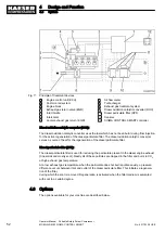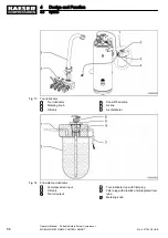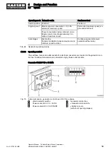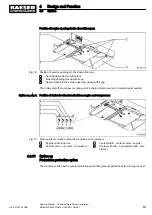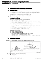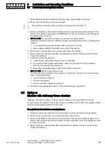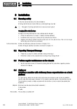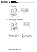
Generator 230 V/3~; 13 kVA:
Fig. 16 Instrument panel – generator control box, 230 V three phase
1
«Mode selector switch»
2
Power socket 230 V / 3~ / PE (32 A)
3
Power socket 230 V AC / 2-phase / PE
4
Power socket 230 V / 3~ / PE (16 A)
5
Generator control box
6
«Generator main switch»
7
«Safety cut-out»
8
«Safety cut-out»
(with shunt opening release)
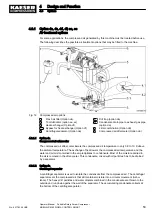
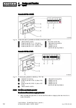
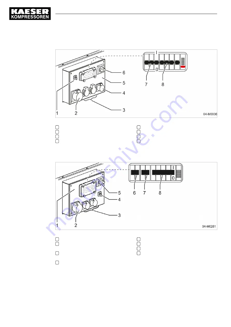
Generator 115 V/2~; 7 kVA:
Fig. 17 Control panel, generator control box, 115 V AC
1
Generator control box
2
Power socket 230 V AC / 2 phase / PE
(32 A)
3
Power socket 230 V AC / 2 phase / PE
(16 A)
4
«Mode selector switch»
5
«Generator main switch»
6
«Safety cut-out»
7
«Safety cut-out»
8
«Safety cut-out»
(with shunt opening release)
4.8.5.3 Note when operating the generator
Do not exceed the maximum supply system load
➤ When operating the generator, do not exceed the maximum supply system load due to con‐
nected consumers.
4
Design and Function
4.8
Options
60
Operator Manual Portable Rotary Screw Compressor
MOBILAIR M82 SIGMA CONTROL SMART
No.: 901783 08 USE

