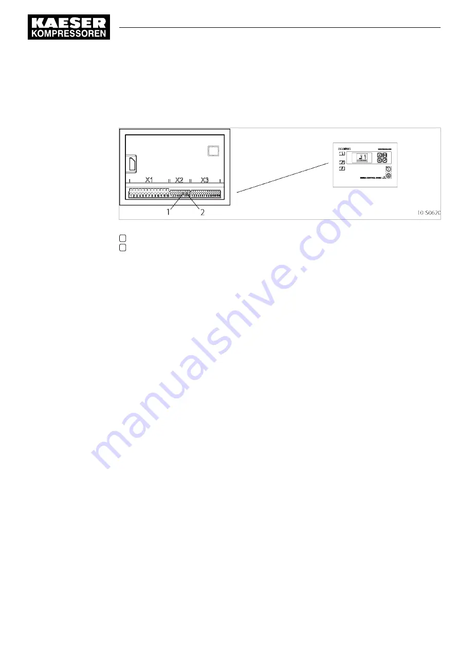
6.5 Connecting the remote contact LOAD-IDLE control
Material Screwdriver: DIN 5264 A – 0.4 x 2.5 mm
Flexible cable: 0.5–1.5 mm
2
(maximum length 100 m; recommended is: NYSLYÖ 2 x 1.0 mm
2
)
Fig. 10 Connections to SIGMA CONTROL BASIC
1
Input I4: pin 7
2
Supply 24 V DC: pin 9
1. Lay the cable so that it does not come under tension when the control cabinet door is opened.
2. Strip 8 mm of insulation from the ends of the conductors.
3. Use a screwdriver to open the spring-loaded terminals and insert the ends of the conductors in
the square openings above the corresponding terminals.
4. Secure the cable so there is no tension on the X2 plug.
5. Seal the cable gland against ingress of dirt or moisture.
6.6 Options
6.6.1 Option H1
Anchoring the machine
➤ Use appropriate fixing bolts to anchor the machine.
Further information Details of the fixing holes are contained in the dimensional drawing in chapter 13.3.
6
Installation
6.5
Connecting the remote contact LOAD-IDLE control
9_6919 04 E
Service Manual Screw Compressor
SX SIGMA CONTROL BASIC
35
Summary of Contents for SX
Page 2: ...Original instructions KKW SSX 1 04 en SBA SCHRAUBEN SCB...
Page 6: ...Contents iv Service Manual Screw Compressor SX SIGMA CONTROL BASIC 9_6919 04 E...
Page 8: ...List of Illustrations vi Service Manual Screw Compressor SX SIGMA CONTROL BASIC 9_6919 04 E...
Page 10: ...List of Tables viii Service Manual Screw Compressor SX SIGMA CONTROL BASIC 9_6919 04 E...


