


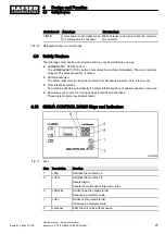


4.2 Function
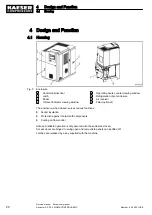
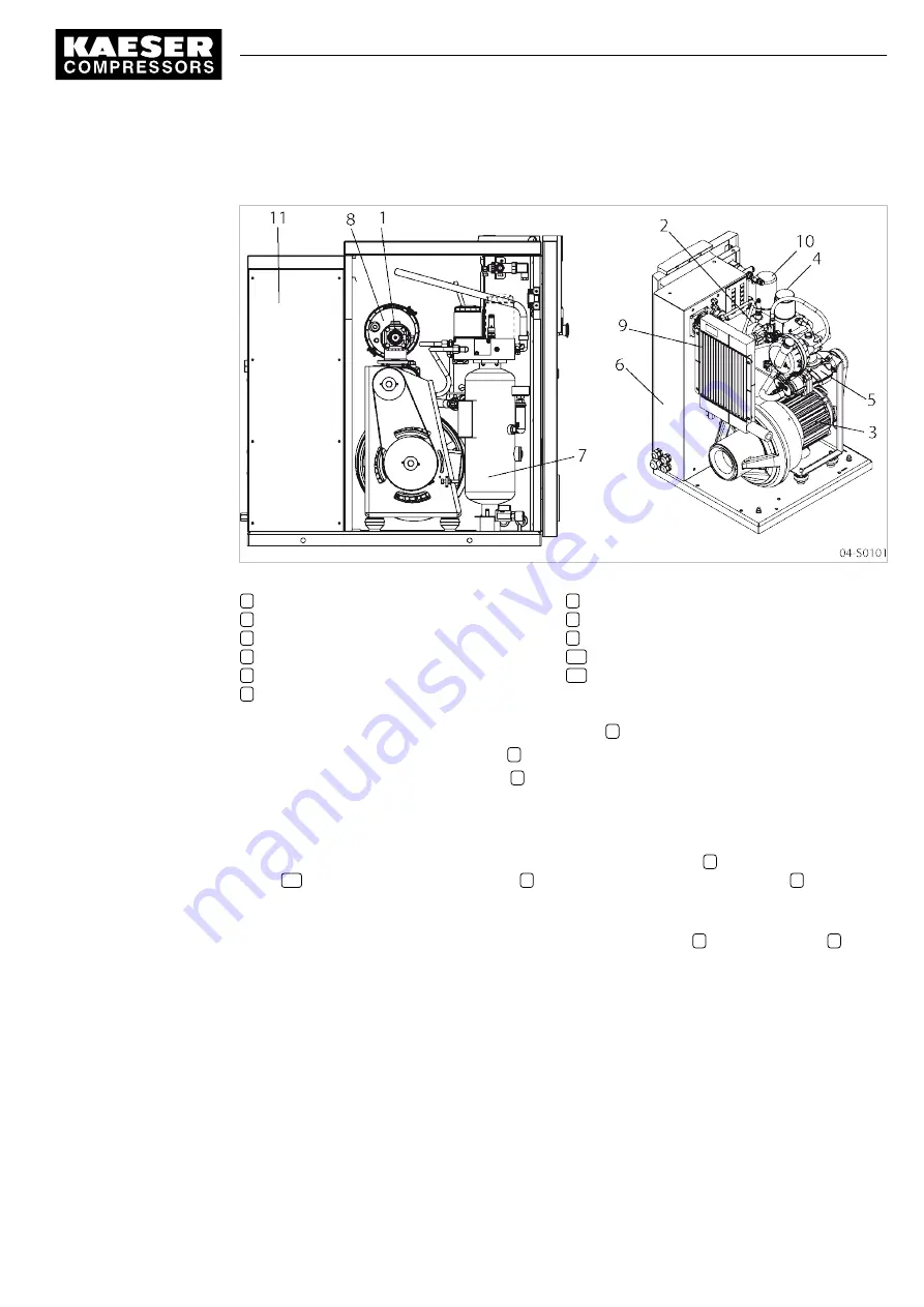
Fig. 6 Machine layout
1
Inlet valve
2
Minimum pressure / check valve
3
Drive motor
4
Oil filter
5
Airend
6
Control cabinet
7
Oil separator tank
8
Air filter
9
Oil/air cooler
10
Oil separator cartridge
11
Add-on cabinet for refrigeration dryer
Ambient air is cleaned as it is drawn in through the filter
8
.
The air is then compressed in the airend
5
.
The airend is driven by an electric motor
3
.
Cooling oil is injected into the airend. It lubricates moving parts and forms a seal between the rotors
themselves and between them and the airend casing. This direct cooling in the compression chamber
ensures a very low airend discharge temperature.
Cooling oil recovered from the compressed air in the oil separator tank
7
and separator car‐
tridge
10
gives up its heat in the oil cooler
9
. The oil then flows through the oil filter
4
and back to
the point of injection. Pressure within the machine keeps the oil circulating. A separate pump is not
necessary. A thermostatic valve maintains optimum cooling oil temperature.
Compressed air passes through the minimum pressure / check valve
2
into the air cooler
9
. The
minimum pressure / check valve ensures that there is always a minimum internal air pressure suffi‐
cient to maintain cooling oil circulation in the machine.
The cooler brings down the compressed air temperature to only 9 to 18 F above ambient. Most of the
moisture carried in the air is removed during this cooling process.
4
Design and Function
4.2
Function
Number: 9_6945 01USE
Service manual Screw compressor
Aircenter SX 3/7.5 SIGMA CONTROL BASIC
21


