Design and Function
4 --- 24
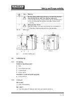
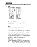
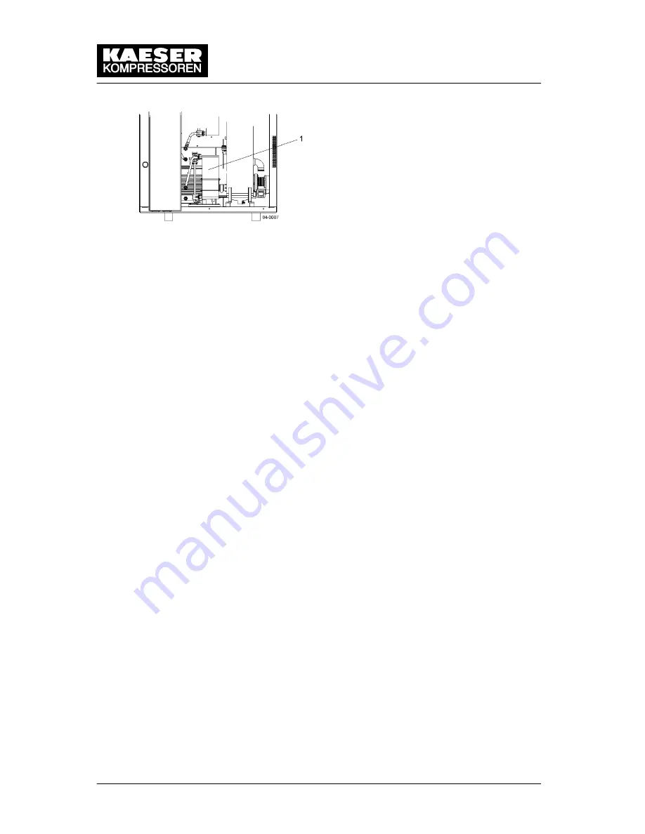
Fig. 6
Internal heat recovery
1
Plate heat exchanger
4.3
Operating States and Control Modes
4.3.1
Operating states
There are three operating states:
LOAD: the inlet valve is open. The airend delivers compressed air to the system.
The compressor motor runs under full load.
IDLING: The inlet valve is closed. The minimum pressure/check valve shuts off the oil
separator from the air system. The oil separator tank is vented.
A small volume of air circulates through the bleed hole in the inlet valve, through the
airend and back to the inlet valve via the venting valve.
The compressor motor runs without load and draws little current.
STANDSTILL: The inlet valve is closed. The minimum pressure/check valve shuts off
the oil separator from the air system. The oil separator tank is vented.
The compresor motor is stopped.
PARTIAL LOAD (option C1): The proportional controller continuously varies the degree
of opening of the inlet valve, and thereby the delivery rate of the compressor, in re-
sponse and in proportion to the air demand. The airend delivers compressed air to the
system.
The load and power consumption of the drive motor rises and falls with the air de-
mand.
The regulating valve is factory set. Consult with KAESER Service before changing.
4.3.2
Tasks of the controller
Using the selected control mode, the controller switches the compressor between its vari-
ous operational states in order to maintain system pressure between the set minimum and
maximum values.
According to the individual compressed air demand one of the various control modes avail-
able will provide the optimum duty cycle for the machine.
4.3.3
Control Modes
The controller can operate in the following modes:
DUAL
VARIO
QUADRO
DUAL
In the DUAL control mode, the compressor is switched back and forth between full load
and idle to maintain system pressure between the set minimum and maximum values.
Summary of Contents for CSD 102
Page 2: ......
Page 85: ......
Page 86: ......
Page 87: ......
Page 88: ......
Page 89: ......
Page 90: ......
Page 95: ......
Page 96: ......
Page 97: ......
Page 98: ......
Page 99: ......
Page 100: ...Appendix 13 92 13 1 2 Pipeline and instrument flow diagram option C1...
Page 101: ......
Page 102: ......
Page 103: ......
Page 104: ......
Page 105: ......
Page 106: ...Appendix 13 98 13 1 3 Dimensional drawing 13 1 3 1 Air cooling option K1...
Page 107: ......
Page 108: ......
Page 109: ...Appendix 13 101 13 1 3 2 Water cooling option K2...
Page 110: ......
Page 111: ......
Page 112: ...Appendix 13 104 13 1 4 Electrical diagram...
Page 113: ......
Page 114: ......
Page 115: ......
Page 116: ......
Page 117: ......
Page 118: ......
Page 119: ......
Page 120: ......
Page 121: ......
Page 122: ......
Page 123: ......
Page 124: ......
Page 125: ......
Page 126: ......
Page 127: ......
Page 128: ......
Page 129: ......
Page 130: ......
Page 131: ......
Page 132: ......
Page 133: ......
Page 134: ......

