Maintenance
10 --- 67
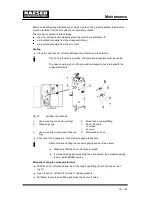
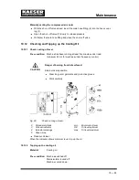
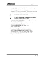
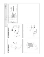
Manually venting the compressed air cooler
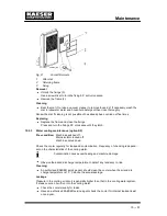
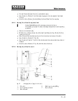
With the shut ---off valve closed, insert the male hose fitting (6) into the hose coupl-
ing (1).
Open the shut ---off valve (7) slowly to release pressure.
Withdraw the male hose fitting and close the shut ---off valve.
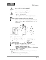
Topping up the cooling oil
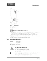
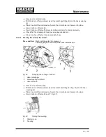
Open the filler plug (4) slowly.
Top up the cooling oil.
Replace the plug gasket if necessary and re---insert the plug.
Start the machine and carry out a test run
Close all access doors; replace and secure all removable panels.
Open the user’s shut ---off valve between the machine and the air main.
Start the machine and allow it to idle for at least one minute. Then switch to LOAD.
After about five minutes, check the oil level and top up if necessary.
Carry out a visual check for leaks.
10.13
Changing the Cooling Oil
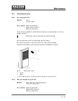
Material:
Cooling oil
Oil catchment container
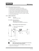
Danger of burns from hot components and oil.
Wear long ---sleeved clothing and gloves.
Work carefully.
Dispose of the old oil in accordance with local environment protection re-
gulations.
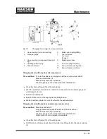
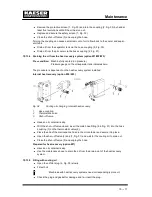
Drain the oil thoroughly from:
Oil separator tank
Oil cooler
Airend
The heat recovery system (if installed).
Compressed air helps to expel the oil.
This pressure can be generated by the machine itself.
Alternatively, an external source of compressed air can be used.
External air is necessary if:
the machine is not operational,
the machine is to be restarted after a long standstill period.
CAUTION
Summary of Contents for CSD 102
Page 2: ......
Page 85: ......
Page 86: ......
Page 87: ......
Page 88: ......
Page 89: ......
Page 90: ......
Page 95: ......
Page 96: ......
Page 97: ......
Page 98: ......
Page 99: ......
Page 100: ...Appendix 13 92 13 1 2 Pipeline and instrument flow diagram option C1...
Page 101: ......
Page 102: ......
Page 103: ......
Page 104: ......
Page 105: ......
Page 106: ...Appendix 13 98 13 1 3 Dimensional drawing 13 1 3 1 Air cooling option K1...
Page 107: ......
Page 108: ......
Page 109: ...Appendix 13 101 13 1 3 2 Water cooling option K2...
Page 110: ......
Page 111: ......
Page 112: ...Appendix 13 104 13 1 4 Electrical diagram...
Page 113: ......
Page 114: ......
Page 115: ......
Page 116: ......
Page 117: ......
Page 118: ......
Page 119: ......
Page 120: ......
Page 121: ......
Page 122: ......
Page 123: ......
Page 124: ......
Page 125: ......
Page 126: ......
Page 127: ......
Page 128: ......
Page 129: ......
Page 130: ......
Page 131: ......
Page 132: ......
Page 133: ......
Page 134: ......

